
Page 371 - Circular Connector Backshells and Accessories
P. 371
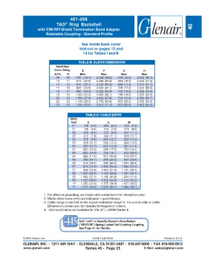
401-008
                                   TAG  Ring Backshell
                                         ®
                        with EMI/RFI Shield Termination Band Adapter                                                 40
                             Rotatable Coupling - Standard Profile


                                                  See inside back cover
                                                 fold-out or pages 13 and
                                                   14 for Tables I and II.


                                                 TABLE III: ELBOW DIMENSIONS
                                   Shell Size
                                  Conn. Desig.     E            F           G           H
                                  A-F-L   H       Max         Max         Max          Max
                                   08    09    .750   (19.1)  2.332 (59.2)  .639 (16.2)  2.222 (56.4)
                                   10    11    .810   (20.6)  2.392 (60.8)  .664 (16.9)  2.252 (57.2)
                                   12    13    .870   (22.1)  2.452 (62.3)  .688 (17.5)  2.272 (57.7)
                                   14    15    .920   (23.4)  2.522 (64.1)  .705 (17.9)  2.302 (58.5)
                                   16    17    .980   (24.9)  2.582 (65.6)  .732 (18.6)  2.322 (59.0)
                                   18    19    1.020 (25.9)  2.602 (66.1)  .748 (19.0)  2.332 (59.2)
                                   20    21    1.080 (27.4)  2.662 (67.6)  .733 (18.6)  2.352 (59.7)
                                   22    23    1.140 (29.0)  2.702 (68.6)  .800 (20.3)  2.392 (60.8)
                                   24    25    1.200 (30.5)  2.812 (71.4)  .823 (20.9)  2.422 (61.5)


                                                     TABLE IV: CABLE ENTRY
                                            Entry
                                            Size      K           L            M
                                             01    .125   (3.2)  .250   (6.4)  .312   (7.9)
                                             31    .188   (4.8)  .312   (7.9)  .374   (9.5)
                                             02    .250   (6.4)  .375   (9.5)  .437 (11.1)
                                             32    .312   (7.9)  .438 (11.1)  .500 (12.7)
                                             03    .375   (9.5)  .500 (12.7)  .562 (14.3)
                                             33    .438 (11.1)  .562 (14.3)  .624 (15.8)
                                             04    .500 (12.7)  .625 (15.9)  .687 (17.4)
                                             34    .562 (14.3)  .688 (17.5)  .750 (19.1)
                                             05    .625 (15.9)  .750 (19.1)  .812 (20.6)
                                             35    .688 (17.5)  .812 (20.6)  .874 (22.2)
                                             06    .750 (19.1)  .875 (22.2)  .937 (23.8)
                                             36    .812 (20.6)  .938 (23.8)  1.000 (25.4)
                                             07    .875 (22.2)  1.000 (25.4)  1.062 (27.0)
                                             37    .938 (23.8)  1.062 (27.0)  1.124 (28.5)
                                             08   1.000 (25.4)  1.125 (28.6)  1.187 (30.1)
                                             38   1.062 (27.0)  1.188 (30.2)  1.250 (31.8)
                                             09   1.125 (28.6)  1.250 (31.8)  1.312 (33.3)
                                             10   1.250 (31.8)  1.375 (34.9)  1.437 (36.5)
                                             11   1.375 (34.9)  1.500 (38.1)  1.562 (39.7)

                            1. For effective grounding, connector with conductive finish should be used.
                            2. Metric dimensions (mm) are indicated in parentheses.
                            3. Cable range is defined as the accommodations range for the wire bundle or cable.
                              Dimensions shown are not intended for inspection criteria.
                            4.  -445 modification not available for MIL-DTL-38999 Series II.


                                                 Add “-445” to Specify Glenair’s Non-Detent,
                                                 ("NESTOR") Spring-Loaded, Self-Locking Coupling.
                                                 See Page 41 for Details.


               © 2005 Glenair, Inc.                      CAGE Code 06324                             Printed in U.S.A.
               GLENAIR, INC. • 1211 AIR WAY • GLENDALE, CA 91201-2497 • 818-247-6000 • FAX 818-500-9912
               www.glenair.com                       Series 40 -  Page 23               E-Mail: sales@glenair.com