
Page 374 - Circular Connector Backshells and Accessories
P. 374
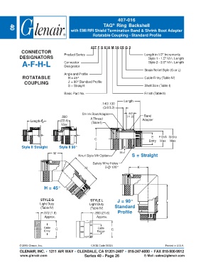
407-016
                                                              TAG  Ring Backshell
                                                                   ®
                                           with EMI/RFI Shield Termination Band & Shrink Boot Adapter
       40
                                                        Rotatable Coupling - Standard Profile


                                                      407 F S 016 M 16 05 G 3
              CONNECTOR
             DESIGNATORS               Product Series                                 Length in 1/2" Increments
                                                                                        Style 1 - 1.5" Min. Length
              A-F-H-L                  Connector                                        Style 2 - 2.5" Min. Length
                                       Designator
            SELF-LOCKING               Angle and Profile                              Strain Relief Style (G or L)
              ROTATABLE                  H = 45°                                      Cable Entry (Table IV)
               COUPLING                  J  = 90° Standard Profile
                                         S = Straight                                 Shell Size (Table I)

                                       Basic Part No.                                 Finish (Table II)
                                                                          Length
                                                             .140/.130
                                                              (3.6/3.3)
                                                 Shrink Boot Adapter        .440
                                     .880             A Thread              (11.2)    Band
                   Length            (22.4)            (Table I)                     Adapter
                                     Max


                                                                                          E    F DIA  G Dia
                                                         C
                                                                                         Entry  Max  Max
              Style II Straight     Style II 90°

                                 M                                      H
                                               Knurl Style Mfr Option          S = Straight
                                                        Safety Wire Holes
                                                   N           3 @ 120°           K


                           H = 45°


                         STYLE G                      STYLE L         J = 90°                      L
                         Light Duty                   Light Duty
                         (Table IV)                   (Table IV)     Standard
                           .072 (1.8)                    .850 (21.6)  Profile
                           Approx.                        Approx.


                           Cable  C                        Cable   C
                           Entry                          Range


             © 2005 Glenair, Inc.                      CAGE Code 06324                            Printed in U.S.A.
             GLENAIR, INC. • 1211 AIR WAY • GLENDALE, CA 91201-2497 • 818-247-6000 • FAX 818-500-9912
             www.glenair.com                       Series 40 - Page 26                E-Mail: sales@glenair.com