
Page 373 - Circular Connector Backshells and Accessories
P. 373
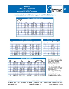
403-001
                                   TAG  Ring Backshell
                                         ®
                                         Environmental                                                               40
                                Rotatable Coupling - Low Profile


                           See inside back cover fold-out or pages 13 and 14 for Tables I and II.


                                                 TABLE III: ELBOW DIMENSIONS
                                 Shell Size
                                Conn. Desig.   E             F            G             H
                                A-F-L  H      Max           Max          Max           Max
                                 08    09  .457   (19.1)  2.680   (68.1)  .500 (12.7)  2.680   (68.1)
                                 10    11  .520   (20.6)  3.070   (78.0)  .595 (15.1)  2.800   (71.1)
                                 12    13  .582   (22.1)  3.130   (79.5)  .610 (15.5)  3.160   (80.3)
                                 14    15  .645   (23.4)  3.230   (82.0)  .700 (17.8)  3.230   (82.0)
                                 16    17  .738   (24.9)  3.330   (84.6)  .885 (22.5)  3.230   (82.0)
                                 18    19  .926   (25.9)  3.430   (87.1)  .975 (24.8)  3.560   (90.4)
                                 20    21  .926   (27.4)  3.590   (91.2)  .975 (24.8)  3.560   (90.4)
                                 22    23  1.020 (29.0)  3.720   (94.5)  1.125 (28.6)  3.650   (92.7)
                                 24    25  1.020 (30.5)  3.720   (94.5)  1.125 (28.6)  3.650   (92.7)
                                 28        1.145 (19.1)  3.890   (98.8)  1.225 (31.1)  3.940 (100.1)
                                 32        1.207 (30.7)  3.990 (101.3)  1.575 (40.0)  4.190 (106.4)
                                 36        1.238 (31.4)  4.080 (103.6)  1.775 (45.1)  4.190 (106.4)


                                    TABLE IV: CABLE ENTRY                           TABLE VI: CLAMP
                    Dash      J            K             Cable Range                          P       Max
                     No.     Max          Max          Min        Max          Sym   Size    Dia     Clamp
                     04    .780 (19.8)  .957 (24.3)  .125   (3.2)  .312   (7.9)  AA   2     .250 (6.4)  08
                     06    .780 (19.8)  1.145 (29.1)  .250   (6.4)  .437 (11.1)  A    3     .357 (9.1)  10
                     08    .780 (19.8)  1.332 (33.8)  .312   (7.9)  .562 (14.3)  B    4    .500 (12.7)  12
                     10    .780 (19.8)  1.332 (33.8)  .350   (8.9)  .625 (15.9)  C    5    .625 (15.9)  16
                     12    .811 (20.6)  1.551 (39.4)  .500 (12.7)  .750 (19.1)  D     6    .750 (19.1)  20
                     16    .905 (23.0)  1.770 (45.0)  .625 (15.9)  .937 (23.8)  E     7    .875 (22.2)  20
                     20   1.092 (27.7)  2.113 (53.7)  .875 (22.2) 1.250 (31.8)  F     8   1.000 (25.4)  24
                     24   1.124 (28.5)  2.363 (60.0)  1.000 (25.4) 1.375 (34.9)  G    9   1.125 (28.6)  28
                     28   1.399 (35.5)  2.770 (70.4)  1.250 (31.8) 1.625 (41.3)  H   10   1.250 (31.8)  32
                     32   1.399 (35.5)  3.020 (76.7)  1.437 (36.5) 1.875 (47.6)  J    11  1.375 (34.9)  40


                                      TABLE V: CABLE ENTRY                          1. Standard minimum length for
                                                                                      Style I is 2.5 inches, and for Style
                 Dash      L           M            N             Cable Range         II is 3 inches.  For shorter length,
                  No.     Max         Max          Max          Min       Max         consult factory. (Applies to
                  03    .760 (19.3)  .843 (21.4)  .630 (16.0)  .156   (4.0)  .250   (6.4)  Straight configuration only).
                  04    .760 (19.3)  .906 (23.0)  .755 (19.2)  .188   (4.8)  .312   (7.9)  2. Metric dimensions (mm) are
                  06    .760 (19.3)  1.093 (27.8)  .942 (23.9)  .281   (7.1)  .438 (11.1)  indicated in parentheses.
                  08    .760 (19.3)  1.187 (30.1)  1.067 (27.1)  .344   (8.7)  .562 (14.3)  3. When maximum cable range
                  10    .760 (19.3)  1.281 (32.5)  1.192 (30.3)  .375   (9.5)  .625 (15.9)  (Table III) is exceeded, Style II will
                  12    .760 (19.3)  1.500 (38.1)  1.380 (35.1)  .438 (11.1)  .750 (19.1)  be supplied.  Note: E, F, G and H
                  16   1.073 (27.3)  1.719 (43.7)  1.535 (39.0)  .562 (14.3)  .938 (23.8)  do not apply to Style II.
                  20   1.323 (33.6)  2.062 (52.4)  1.848 (46.9)  .750 (19.1) 1.250 (31.8)  4. Cable range is defined as the
                  24   1.323 (33.6)  2.312 (58.7)  2.255 (57.3)  .781 (19.8) 1.375 (34.9)  accommodations range for the
                  28   1.572 (39.9)  2.719 (69.1)  2.505 (63.5)  .969 (24.6) 1.625 (41.3)  wire bundle or cable.
                  32   1.572 (39.9)  2.969 (75.4)  2.755 (70.0)  1.125 (28.6) 1.875 (47.6)  Dimensions shown are not
                  40   1.572 (39.9)  2.531 (64.3)  3.255 (82.7)  1.469 (37.3) 2.375 (60.3)  intended for inspection criteria.


               © 2005 Glenair, Inc.                      CAGE Code 06324                             Printed in U.S.A.
               GLENAIR, INC. • 1211 AIR WAY • GLENDALE, CA 91201-2497 • 818-247-6000 • FAX 818-500-9912
               www.glenair.com                       Series 40 -  Page 25               E-Mail: sales@glenair.com