
Page 367 - Circular Connector Backshells and Accessories
P. 367
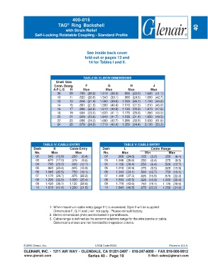
400-015
                                   TAG  Ring Backshell
                                         ®
                                        with Strain Relief                                                           40
                      Self-Locking Rotatable Coupling - Standard Profile


                                                    See inside back cover
                                                   fold-out or pages 13 and
                                                     14 for Tables I and II.


                                                  TABLE III: ELBOW DIMENSIONS
                                  Shell Size
                                 Conn. Desig.      F             G            H            J
                                A-F-L-S   H       Max          Max          Max           Max
                                   08     09   .795 (20.2)  1.510 (38.4)  .906 (23.0)  1.620 (41.1)
                                   10     11   .820 (20.8)  1.540 (39.1)  .966 (24.5)  1.680 (42.7)
                                   12     13   .844 (21.4)  1.560 (39.6)  1.026 (26.1)  1.740 (44.2)
                                   14     15   .861 (21.9)  1.590 (40.4)  1.076 (27.3)  1.810 (46.0)
                                   16     17   .888 (22.6)  1.610 (40.9)  1.136 (28.9)  1.870 (47.5)
                                   18     19   .904 (23.0)  1.620 (41.1)  1.176 (29.9)  1.890 (48.0)
                                   20     21   .929 (23.6)  1.640 (41.7)  1.236 (31.4)  1.950 (49.5)
                                   22     23   .956 (24.3)  1.680 (42.7)  1.296 (32.9)  2.030 (51.6)
                                   24     25   .979 (24.9)  1.710 (43.4)  1.356 (34.4)  2.100 (53.3)


                          TABLE IV: CABLE ENTRY                           TABLE V: CABLE ENTRY
                     Dash        K        Cable Entry        Dash         L               Cable Range
                      No.      Max           Max              No.        Max          Min           Max
                      02     .545 (13.8)   .250  (6.4)         02     .968 (24.6)   .125  (3.2)   .250  (6.4)
                      03     .670 (17.0)   .375  (9.5)         03    1.046 (26.6)   .250  (6.4)   .375  (9.5)
                      04     .795 (20.2)   .500 (12.7)         04    1.156 (29.4)   .250  (6.4)   .500 (12.7)
                      05     .920 (23.4)   .625 (15.9)         05    1.218 (30.9)   .375  (9.5)   .625 (15.9)
                      06    1.045 (26.5)   .750 (19.1)         06    1.343 (34.1)   .500 (12.7)   .750 (19.1)
                      07    1.170 (29.7)   .875 (22.2)         07    1.468 (37.3)   .625 (15.9)   .875 (22.2)
                      08    1.295 (32.9)  1.000 (25.4)         08    1.593 (40.5)   .625 (15.9)  1.000 (25.4)
                      09    1.420 (36.1)  1.125 (28.6)         09    1.718 (43.6)   .750 (19.1)  1.125 (28.6)
                      10    1.670 (42.4)  1.250 (31.8)         10    1.843 (46.8)   .875 (22.2)  1.250 (31.8)


                              1. When maximum cable entry (page 21) is exceeded, Style 2 will be supplied.
                                 Dimensions F, G, H and J will not apply.  Please consult factory.
                              2. Metric dimensions (mm) are indicated in parentheses.
                              3. Cable range is defined as the accommodations range for the wire bundle or cable.
                                 Dimensions shown are not intended for inspection criteria.


               © 2005 Glenair, Inc.                      CAGE Code 06324                             Printed in U.S.A.
               GLENAIR, INC. • 1211 AIR WAY • GLENDALE, CA 91201-2497 • 818-247-6000 • FAX 818-500-9912
               www.glenair.com                       Series 40 -  Page 19               E-Mail: sales@glenair.com