
Page 363 - Circular Connector Backshells and Accessories
P. 363
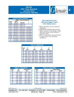
400-002
                                         ®
                                   TAG  Ring Backshell
                                        with Strain Relief                                                           40
                                  Direct Coupling - Split Shell


                      TABLE III: FRONT ADAPTER
                           J Max - Conn. Designator
                Shell    A-E-F                                         See inside back cover
                 Size    J-H-L-S   D-B-G-K      C                    fold-out or pages 13 and
                08/09 1.180 (30.0) 1.250 (31.8)                         14 for Tables I and II.
                10/11 1.180 (30.0) 1.250 (31.8)
                12/13 1.180 (30.0) 1.250 (31.8) 1.735 (44.1)    1. Metric dimensions (mm) are indicated in
                14/15 1.180 (30.0) 1.250 (31.8) 1.915 (48.6)       parentheses.
                16/17 1.380 (35.0) 1.560 (39.6) 1.915 (48.6)    2. Cable range is defined as the accommo-
                18/19 1.380 (35.0) 1.560 (39.6) 1.915 (48.6)       dations range for the wire bundle or cable.
                20/21 1.380 (35.0) 1.560 (39.6) 1.915 (48.6)       Dimensions shown are not intended for
                22/23 1.380 (35.0) 1.560 (39.6) 1.915 (48.6)       inspection criteria.
                24/25 1.380 (35.0) 1.560 (39.6) 1.915 (48.6)    3. When using Connector Designator B refer
                28/29 1.610 (40.9) 1.560 (39.6) 1.915 (48.6)       to pages 18 and 19 for part number
                32/33 1.610 (40.9) 1.750 (44.5) 1.915 (48.6)       development.
                  36  1.610 (40.9) 1.750 (44.5) 1.915 (48.6)
                  40  1.610 (40.9) 2.190 (55.6) 1.915 (48.6)


                                                    TABLE IV: DIMENSIONS

                                      Dash    D           E          F           G
                                      No.    Max        Max         Max         Max
                                       02 .440 (11.2) 1.500 (38.1)  .680 (17.3) 1.440 (36.6)
                                       03 .500 (12.7) 1.560 (39.6)  .750 (19.1) 1.500 (38.1)
                                       04 .560 (14.2) 1.630 (41.4)  .810 (20.6) 1.570 (39.9)
                                       05 .620 (15.7) 1.660 (42.2)  .870 (22.1) 1.600 (40.6)
                                       06 .680 (17.3) 1.760 (44.7)  .930 (23.6) 1.700 (43.2)
                                       07 .750 (19.1) 1.820 (46.2)  1.000 (25.4) 1.760 (44.7)
                                       08 .820 (20.8) 1.880 (47.8)  1.060 (26.9) 1.820 (46.2)
                                       09 .880 (22.4) 1.940 (49.3)  1.120 (28.4) 1.880 (47.8)
                                       10 .940 (23.9) 2.000 (50.8)  1.180 (30.0) 1.940 (49.3)


                         TABLE V: CABLE ENTRY                           TABLE VI: CABLE ENTRY
                   Dash        M         Cable Entry        Dash         N              Cable Range
                    No.       Max           Max              No.       Max           Min           Max
                     02    .545 (13.8)    .250  (6.4)        02      .968 (24.6)  .125  (3.2)    .250  (6.4)
                     03    .670 (17.0)    .375  (9.5)        03     1.046 (26.6)  .250  (6.4)    .375  (9.5)
                     04    .795 (20.2)    .500 (12.7)        04     1.156 (29.4)  .250  (6.4)    .500 (12.7)
                     05    .920 (23.4)    .625 (15.9)        05     1.218 (30.9)  .375  (9.5)    .625 (15.9)
                     06   1.045 (26.5)    .750 (19.1)        06     1.343 (34.1)  .500 (12.7)    .750 (19.1)
                     07   1.170 (29.7)    .875 (22.2)        07     1.468 (37.3)  .625 (15.9)    .875 (22.2)
                     08   1.295 (32.9)   1.000 (25.4)        08     1.593 (40.5)  .625 (15.9)   1.000 (25.4)
                     09   1.420 (36.1)   1.125 (28.6)        09     1.718 (43.6)  .750 (19.1)   1.125 (28.6)
                     10   1.670 (42.4)   1.250 (31.8)        10     1.843 (46.8)  .875 (22.2)   1.250 (31.8)


               © 2005 Glenair, Inc.                      CAGE Code 06324                             Printed in U.S.A.
               GLENAIR, INC. • 1211 AIR WAY • GLENDALE, CA 91201-2497 • 818-247-6000 • FAX 818-500-9912
               www.glenair.com                       Series 40 -  Page 15               E-Mail: sales@glenair.com