
Page 544 - Circular Connector Backshells and Accessories
P. 544
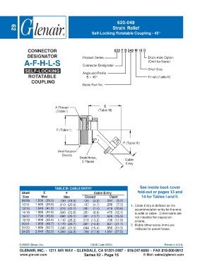
620-049
                                                                    Strain Relief
        62
                                                       Self-Locking Rotatable Coupling - 45°


                  CONNECTOR                                          620 F B 049 M 16 D
                 DESIGNATOR                       Product Series                         Drain Hole Option
               A-F-H-L-S                          Connector Designator                   (Omit for None)

                SELF-LOCKING                      Angle and Profile                      Shell Size
                  ROTATABLE                         B = 45°                              Finish (Table II)
                    COUPLING
                                                  Basic Part No.


                                  A Thread                     E
                                  (Table I)                (Table III)


                                  E (Table I)


                                                                          F (Table III)

                                   Anti-Rotation
                                      Device
                                                Drain Holes,
                                                 3 Places                  Cable
                                                                           Entry


                                 TABLE III: CABLE ENTRY                             See inside back cover
              Shell        E            F                Cable Entry              fold-out or pages 13 and
              Size        Max          Max         Closed         Open               14 for Tables I and II.
              08/09   1.536 (39.0)  .730 (18.5)   .125  (3.2)   .204  (5.2)
              10/11   1.566 (39.8)  .810 (20.6)   .187  (4.7)   .286  (7.3)   1. Cable Entry is defined as the
              12/13   1.646 (41.8)  .870 (22.1)   .291  (7.4)   .416 (10.6)      accommodation entry for the wire
              14/15   1.686 (42.8)  .930 (23.6)   .351  (8.9)   .476 (12.1)      bundle or cable.  Dimensions are
              16/17   1.796 (45.6)  .990 (25.1)   .501 (12.7)   .626 (15.9)      not intended for inspection
              18/19   1.906 (48.4)  1.110 (28.2)  .518 (13.2)   .706 (17.9)      criteria.
              20/21   1.956 (49.7)  1.170 (29.7)  .581 (14.8)   .831 (21.1)   2. Metric dimensions (mm) are
              22/23   1.996 (50.7)  1.240 (31.5)  .644 (16.4)   .956 (24.3)      indicated in parentheses.
              24/25   2.046 (52.0)  1.300 (33.0)  .706 (17.9)  1.081 (27.5)


             © 20053 Glenair, Inc.                     CAGE Code 06324                            Printed in U.S.A.
             GLENAIR, INC. • 1211 AIR WAY • GLENDALE, CA 91201-2497 • 818-247-6000 • FAX 818-500-9912
             www.glenair.com                       Series 62 - Page 16                E-Mail: sales@glenair.com