
Page 546 - Circular Connector Backshells and Accessories
P. 546
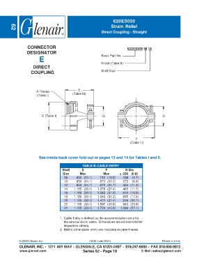
620ES050
                                                                    Strain Relief
                                                              Direct Coupling - Straight
        62


                  CONNECTOR                                                  620ES050 M 16
                 DESIGNATOR                                   Basic Part No.
                         E
                                                              Finish (Table II)
                     DIRECT
                    COUPLING                                  Shell Size


                                                E
                       A Thread
                       (Table I)             (Table III)


                          C (Table I)                          G                                   G


                                                                                   F
                                                                               (Table III)


                        See inside back cover fold-out or pages 13 and 14 for Tables I and II.

                                                   TABLE III: CABLE ENTRY
                                      Shell       E             F           G Dia
                                       Size      Max           Max       ± .030 (0.8)
                                        08    .950 (24.1)    .742 (18.8)  .186  (4.7)
                                        10    .950 (24.1)    .873 (22.2)  .270  (6.9)
                                        12    .950 (24.1)    .972 (24.7)  .450 (11.4)
                                        14   1.185 (30.1)  1.078 (27.4)   .460 (11.7)
                                        16   1.185 (30.1)  1.242 (31.5)   .610 (15.5)
                                        18   1.185 (30.1)  1.345 (34.2)   .690 (17.5)
                                        20   1.185 (30.1)  1.472 (37.4)   .816 (20.7)
                                        22   1.185 (30.1)  1.597 (40.6)   .940 (23.9)
                                        24   1.185 (30.1)  1.724 (43.8)  1.066 (27.1)


                                     1. Cable Entry is defined as the accommodation entry for
                                       the wire bundle or cable.  Dimensions are not intended for
                                       inspection criteria.
                                     2. Metric dimensions (mm) are indicated in parentheses.


             © 20053 Glenair, Inc.                     CAGE Code 06324                            Printed in U.S.A.
             GLENAIR, INC. • 1211 AIR WAY • GLENDALE, CA 91201-2497 • 818-247-6000 • FAX 818-500-9912
             www.glenair.com                       Series 62 - Page 18                E-Mail: sales@glenair.com