Page 543 - Circular Connector Backshells and Accessories
P. 543

620-048
                                         Strain Relief                                                               62
                      Self-Locking Rotatable Coupling - Straight and 90°
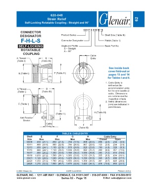

                                                                        620 F S 048 M 16
                  CONNECTOR
                  DESIGNATOR                         Product Series                       Shell Size (Table III)
                   F-H-L-S                           Connector Designator                 Finish (Table II)

                 SELF-LOCKING                        Angle and Profile                    Basic Part No.
                   ROTATABLE                           S = Straight
                                                       A = 90°
                    COUPLING
                                                                             Cable
               A Thread                E                                      Entry
                (Table I)           (Table III)


                                                                                             See inside back
                                                                                             cover fold-out or
                 E (Table I)                   F (Table III)                                 pages 13 and 14
                                                                                            for Tables I and II.

                                                                                          1. Cable Entry is
                                                                                            defined as the
                A Thread                G                                                   accommodation entry
                (Table I)           (Table III)                                             for the wire bundle or
                                                                                            cable.  Dimensions
                                                                                            are not intended for
                                                                                            inspection criteria.
                                                                                          2. Metric dimensions
                 E (Table I)                                                                (mm) are indicated in
                                                                                            parentheses.
                                                    H
                                                (Table III)                      H (Table III)
                  Anti-Rotation
                     Device
                                        Cable                          F
                                        Entry                       (Table III)


                                                     TABLE III: CABLE ENTRY
                        Shell      E             F            G            H             Cable Entry
                        Size      Max          Max           Max          Max        Closed       Open
                        08/09   .830 (21.1)  .850 (21.6)  .704 (17.9)  .808 (20.5)  .098  (2.5)  .234  (5.9)
                        10/11   .900 (22.9)  .900 (22.9)  .786 (20.0)  .867 (22.0)  .153  (3.9)  .234  (5.9)
                        12/13   .950 (24.1)  1.100 (27.9)  .979 (24.9)  .929 (23.6)  .190  (4.8)  .328  (8.3)
                        14/15   .950 (24.1)  1.150 (29.2)  1.039 (26.4)  .992 (25.2)  .260  (6.6)  .457 (11.6)
                        16/17   .990 (25.2)  1.300 (33.0)  1.188 (30.2)  1.056 (26.8)  .283  (7.2)  .614 (15.6)
                        18/19  1.070 (27.2)  1.500 (38.1)  1.300 (33.0)  1.233 (31.3)  .325  (8.3)  .634 (16.1)
                        20/21  1.120 (28.5)  1.600 (40.6)  1.425 (36.2)  1.296 (32.9)  .343  (8.7)  .698 (17.7)
                        22/23  1.240 (31.5)  1.700 (43.2)  1.550 (39.4)  1.358 (34.5)  .381  (9.7)  .823 (20.9)
                        24/25  1.270 (32.3)  1.800 (45.7)  1.675 (42.5)  1.420 (36.1)  .418 (10.6)  .853 (21.7)


               © 2005 Glenair, Inc.                      CAGE Code 06324                             Printed in U.S.A.
               GLENAIR, INC. • 1211 AIR WAY • GLENDALE, CA 91201-2497 • 818-247-6000 • FAX 818-500-9912
               www.glenair.com                       Series 62 -  Page 15               E-Mail: sales@glenair.com
   538   539   540   541   542   543   544   545   546   547   548