
Page 524 - Circular Connector Backshells and Accessories
P. 524
Series 463
EMI/RFI Environmental G-Spring Backshell
with Strain Relief
460
Assembly Instructions
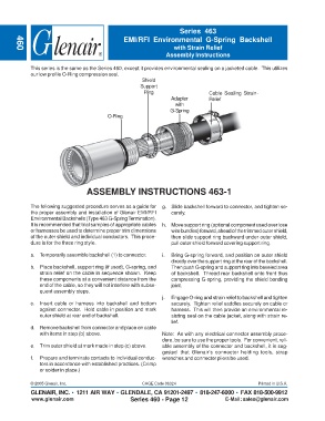
This series is the same as the Series 460, except it provides environmental sealing on a jacketed cable. This utilizes
our low profile O-Ring compression seal.
Shield
Support
Ring Cable Sealing Strain-
Adapter Relief
with
G-Spring
O-Ring
ASSEMBLY INSTRUCTIONS 463-1
The following suggested procedure serves as a guide for g. Slide backshell forward to connector, and tighten se-
the proper assembly and installation of Glenair EMI/RFI curely.
Environmental Backshells (Type 463 G-Spring Termination).
It is recommended that trial samples of appropriate cables h. Move support ring (optional component used over lose
or harnesses be used to determine proper trim dimensions wire bundles) forward, ahead of the trimmed outer shield,
of the outer shield and individual conductors. This proce- then slide support ring backward under outer shield,
dure is for the three ring style. pull outer shield forward covering support ring.
a. Temporarily assemble backshell (1) to connector. i. Bring G-spring forward, and position on outer shield
directly over the support ring at the rear of the backshell.
b. Place backshell, support ring (if used), G-spring, and Then push G-spring and support ring into beveled area
strain relief on the cable in sequence shown. Keep of backshell. Thread rear backshell onto front thus
these components at a convenient distance from the compressing G-spring, providing the shield bonding
end of the cable, so they will not interfere with subse- joint.
quent assembly steps.
j. Engage O-ring and strain relief to backshell and tighten
c. Insert cable or harness into backshell and bottom securely. Tighten relief saddles securely on cable or
against connector. Hold cable in position and mark harness. This will then provide an environmental re-
outer shield at rear end of backshell. sisting seal on the cable jacket, along with strain re-
lief.
d. Remove backshell from connector and place on cable
with items in step (b) above. Note: As with any electrical connector assembly proce-
dure, be sure to use the proper tools. For convenient, reli-
e. Trim outer shield at mark made in step (c) above. able assembly of the connector and backshell, it is sug-
gested that Glenair’s connector holding tools, strap
f. Prepare and terminate contacts to individual conduc- wrenches and connector pliers be used.
tors in accordance with established practices. (Crimp
or solder in place.)
© 2005 Glenair, Inc. CAGE Code 06324 Printed in U.S.A.
GLENAIR, INC. • 1211 AIR WAY • GLENDALE, CA 91201-2497 • 818-247-6000 • FAX 818-500-9912
www.glenair.com Series 460 - Page 12 E-Mail: sales@glenair.com