Page 394 - Circular Connector Backshells and Accessories
P. 394

440-001
                                                          EMI/RFI Crimp Ring Adapter
                                                          Direct Coupling - Standard Profile
        440

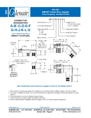
                                                                   440 F S 001 M 16 32-6
                    CONNECTOR
                   DESIGNATORS                     Product Series                         Length: S only
                                                                                            (1/2 inch increments:
               A-B -C-D-E-F                        Connector Designator                     e.g. 6 = 3 inches)
                       *
                G-H-J-K-L-S                        Angle and Profile                      Cable Entry (Table V)
                                                      H = 45°
                                                      J = 90°                             Shell Size (Table I)
                * Conn. Desig. B See Note 5           S = Straight
                DIRECT COUPLING                                                           Finish (Table II)
                                                   Basic Part No.
                                                                             J        E
                                  Length *         * Length ± .060        (Table III)  (Table IV)
               A Thread                                (1.52)
                (Table I)                            Min. Order
                                              K
                               O-Ring         **   Length 1.5 Inch                                 F (Table IV)
                                                    (See Note 4)    B
                                                                 (Table I)

                  B                                    L**
                (Table I)                                    M**


                    Length ± .060 (1.52)              Crimp Ring              J         G
                  Min. Order Length 2.0 Inch                              (Table III)  (Table IV)
                        (See Note 4)
                                                       P**   R**
                                                                    B
                                                                  (Table I)
                                                       ** (Table V)
                STYLE 2
              (STRAIGHT                      N**
              See Note 1)                                                                           H (Table IV)


                        See inside back cover fold-out or pages 13 and 14  for Tables I and II.


             1. When maximum cable entry (page 22- Introduction) is exceeded, Style 2 will be supplied.  (Function S only).
             2. For proper installation of crimp ring, use Thomas & Betts (or equivalent) installation dies listed (Table V) for each
               dash no.
             3. Metric dimensions (mm) are indicated in parentheses.
             4. Consult factory for shorter lengths on straight backshells.
             5. When using Connector Designator B refer to pages 18 and 19 for part number development.


             © 2005 Glenair, Inc.                      CAGE Code 06324                            Printed in U.S.A.
             GLENAIR, INC. • 1211 AIR WAY • GLENDALE, CA 91201-2497 • 818-247-6000 • FAX 818-500-9912
             www.glenair.com                       Series 440 - Page 8                E-Mail: sales@glenair.com
   389   390   391   392   393   394   395   396   397   398   399