
Page 389 - Circular Connector Backshells and Accessories
P. 389
Series 440
EMI/RFI Crimp Ring Adapter 440
Assembly Instructions
Crimp Ring Backshells
Assembly Instructions 44-1
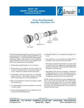
Overall
Shield (3)
Crimp
Ring (2)
Backshell (1)
Connector
The following suggested prodedure serves as a guide for g. Assemble backshell (1) to connector and tighten se-
proper assembly and installation of Glenair EMI/RFI Crimp curely.
Ring Backshells. It is recommended that trial samples of
appropriate cables or harnesses be used to determine h. Flare shield over rear crimping area of backshell (1)
proper trim dimensions of the outer shield, individual con- and slide crimp ring (2) into place over shield.
ductors, and cable jacket where applicable.
i. Hold crimp ring and shield in position as in step (h) and
a. Temporarily assemble backshell (1) to connector. crimp with proper tool, making sure accepted crimping
practices are observed. Trim any exposed shield strands
b. Place crimp ring (2) on cable or harness, and keep it at at forward end of crimp ring.
a convenient distance from the end of the cable so it
will not interfere with subsequent assembly steps. j. Depending on the particular application, subsequent
molding, potting or shrink boot installation may be ac-
c. Insert cable or harness into backshell (1) and bottom complished at this point, using the knurled surface or
against connector. Hold cable in position and mark molding grooves provided on the backshell body.
outer shield (or jacket) at rear end of backshell.
NOTE: As with any electrical connector assembly proce-
d. Remove backshell from connector and place on cable dure, be sure to use the proper tools. Be sure the proper
with crimp ring (2). crimp tool and die head is used. For convenient reliable
assembly of the backshell to the connector it is suggested
e. Trim outer shield (and jacket if necessary) at mark made that Glenair's connector holding tools, strap wrenches and
in step (c) above. connector pliers be used.
f. Prepare and terminate individual conductors in accor-
dance with established practices.
© 2005 Glenair, Inc. CAGE Code 06324 Printed in U.S.A.
GLENAIR, INC. • 1211 AIR WAY • GLENDALE, CA 91201-2497 • 818-247-6000 • FAX 818-500-9912
www.glenair.com Series 440 - Page 3 E-Mail: sales@glenair.com