
Page 390 - Circular Connector Backshells and Accessories
P. 390
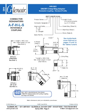
440-063

                                                           EMI/RFI Crimp Ring Adapter
                                                        Rotatable Coupling - Standard Profile
     440


                                                                  440 F S 063 M 16 32-6
               CONNECTOR                          Product Series                          Length: S only
              DESIGNATORS                                                                   (1/2 inch increments:
             A-F-H-L-S                            Connector Designator                      e.g. 6 = 3 inches)


                ROTATABLE                         Angle and Profile                       Cable Entry (Table IV)
                                                    H = 45°
                 COUPLING                           J = 90°                               Shell Size (Table I)
                                                    S = Straight
                                                                                          Finish (Table II)
                                                  Basic Part No.

                                                                      Length *              See inside back
                       Length ± .060 (1.52)                                                cover fold-out or
                    Min. Order Length 2.0 inch    A Thread                      K          pages 13 and 14
                          (See Note 5)            (Table I)     O-Ring        (Table      for Tables I and II.
                                                                               IV)

                                                 C Typ.                                   L**   M**
                                                (Table I)


               STYLE 2                                                                  Crimp Ring
              (STRAIGHT                             * Length ± .060 (1.52)
              See Note 1)                        Min. Order Length 1.5 Inch
                                                        (See Note 5)
                                                                                         P**   R**


                                                E
                         .88 (22.4)           (Table III)                              ** (Table IV)
                           Max                                                 N**


                                                             F (Table III)
                                                                                           G
                                                                                        (Table III)


                STYLE 2
               (45° & 90°
               See Note 1)

                                                                                                      H (Table III)
                               Add “-445” to Specify Glenair’s Non-Detent,
                               (“NESTOR”) Spring-Loaded, Self-Locking Coupling.
                               See Page 41 for Details.


                                        Metric dimensions (mm) are indicated in parentheses.


          © 2005 Glenair, Inc.                        CAGE Code 06324                               Printed in U.S.A.
           GLENAIR, INC. • 1211 AIR WAY • GLENDALE, CA 91201-2497 • 818-247-6000 • FAX 818-500-9912
          www.glenair.com                          Series 440 - Page 4                 E-Mail: sales@glenair.com