
Page 392 - Circular Connector Backshells and Accessories
P. 392
440-063
EMI/RFI Crimp Ring Adapter
Rotatable Coupling - Split Shell
440
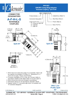
440 F D 063 M 16 32
CONNECTOR
DESIGNATORS Product Series Cable Entry (Table IV)
A-F-H-L-S Connector Designator Shell Size (Table I)
ROTATABLE Angle and Profile Finish (Table II)
COUPLING C = Ultra-Low Split 90°
D = Split 90° Basic Part No.
F = Split 45°
A Thread D F
(Table I) (Table III) (Table III)
C Typ. E (Table III)
(Table I)
L*
G
Split 45° Split 90° (Table
III)
P* M*
N*
.88 (22.4) R*
Max * (Table IV) S*
K
(Table III)
H (Table III)
STYLE 2
(See Note 1)
Max Wire
1. When maximum cable entry (page 21) is exceeded, Style 2 will Bundle
be supplied (not available in Function C). Dimensions D, E, F (Table III, J
and G will not apply. Please consult factory. Note 1) (Table III)
2. For proper installation of crimp ring, use Thomas & Betts (or
equivalent) installation dies listed (Table IV) for each dash no.
3. Metric dimensions (mm) are indicated in parentheses.
4. Dimensions shown are not intended for inspection criteria.
5. Angular function “C”, low-profile split elbow, not available with
“S” connector designator.
Ultra Low-
Profile Split
90°
© 2005 Glenair, Inc. CAGE Code 06324 Printed in U.S.A.
GLENAIR, INC. • 1211 AIR WAY • GLENDALE, CA 91201-2497 • 818-247-6000 • FAX 818-500-9912
www.glenair.com Series 440 - Page 6 E-Mail: sales@glenair.com