
Page 377 - Circular Connector Backshells and Accessories
P. 377
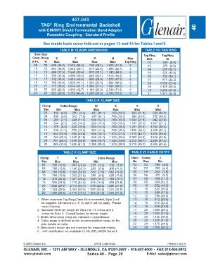
407-043
                         TAG   Ring  Environmental  Backshell
                               ®
                        with EMI/RFI Shield Termination Band Adapter                                                 40
                             Rotatable Coupling - Standard Profile

                           See inside back cover fold-out or pages 13 and 14 for Tables I and II.

                                     TABLE III: ELBOW DIMENSIONS                       TABLE VII: TAG RING
                     Shell Size                                                       Tag Ring   Tag Ring
                    Conn. Desig.  E          F           G          H        Max        Size        I.D.
                    A-F-L   H    Max        Max         Max       Max      Tag Ring      02      .250   (6.4)
                     08    09  .639 (16.2)  1.510 (38.4)  .750 (19.1)  1.620 (41.1)  2   03      .375   (9.5)
                     10    11  .664 (16.9)  1.540 (39.1)  .810 (20.6)  1.680 (42.7)  3   04      .500 (12.7)
                     12    13  .688 (17.5)  1.560 (39.6)  .870 (22.1)  1.740 (44.2)  4   05      .625 (15.9)
                     14    15  .705 (17.9)  1.590 (40.4)  .920 (23.4)  1.810 (46.0)  5   06      .750 (19.1)
                     16    17  .732 (18.6)  1.610 (40.9)  .980 (24.9)  1.870 (47.5)  6   07      .875 (22.2)
                     18    19  .748 (19.0)  1.620 (41.1)  1.020 (25.9)  1.890 (48.0)  6  08     1.000 (25.4)
                     20    21  .773 (19.6)  1.640 (41.7)  1.080 (27.4)  1.950 (49.5)  7  09     1.125 (28.6)
                     22    23  .800 (20.3)  1.680 (42.7)  1.140 (29.0)  2.030 (51.6)  8  10     1.250 (31.8)
                     24    25  .823 (20.9)  1.710 (43.4)  1.200 (30.5)  2.100 (53.3)  9  11     1.375 (34.9)
                                                    TABLE IV: CLAMP SIZE
                          Clamp      C a  R   e l b  a n g e  W      X            Y            Z
                           Size    Min       Max         Max        Max          Max         Max
                           03   .156   (4.0)  .250   (6.4)  .437 (11.1)  .760 (19.3)  .843 (21.4)  .630 (16.0)
                           04   .188   (4.8)  .312   (7.9)  .437 (11.1)  .760 (19.3)  .906 (23.0)  .755 (19.2)
                           06   .281   (7.1)  .438 (11.1)  .500 (12.7)  .760 (19.3)  1.093 (27.8)  .942 (23.9)
                           08   .344   (8.7)  .562 (14.3)  .563 (14.3)  .760 (19.3)  1.187 (30.1)  1.067 (27.1)
                           10   .375   (9.5)  .625 (15.9)  .563 (14.3)  .760 (19.3)  1.281 (32.5)  1.192 (30.3)
                           12   .438 (11.1)  .750 (19.1)  .563 (14.3)  .760 (19.3)  1.500 (38.1)  1.380 (35.1)
                           16   .562 (15.9)  .938 (23.8)  .656 (16.7)  1.073 (27.3)  1.719 (43.7)  1.535 (39.0)
                           20   .750 (22.2) 1.250 (31.8)  .656 (16.7)  1.323 (33.6)  2.062 (52.4)  1.848 (46.9)
                           24   .781 (25.4) 1.375 (34.9)  .656 (16.7)  1.323 (33.6)  2.312 (58.7)  2.255 (57.3)
                           28   .969 (31.8) 1.625 (41.3)  1.188 (30.2)  1.572 (39.9)  2.719 (69.1)  2.505 (63.6)


                                       TABLE V: CLAMP SIZE                     TABLE VI: CABLE ENTRY
                         Clamp     T          V            Cable Range         Dash  Clamp      J
                          Size    Max        Max         Min       Max          No.   Size     Dia
                          04    .780 (19.8)  .957 (23.4)  .125   (3.2)  312   (7.9)  03  03  .188   (4.8)
                          06    .780 (19.8)  1.145 (29.1)  .250   (6.4)  .438 (11.1)  04  03  .250   (6.4)
                          08    .780 (19.8)  1.332 (33.8)  .312   (7.9)  .562 (14.3)  05  04  .312   (7.9)
                          10    .780 (19.8)  1.332 (33.8)  .350   (8.9)  .625 (15.9)  06  06  .375   (9.5)
                          12    .811 (20.6)  1.551 (39.4)  .500 (12.7)  .750 (19.1)  07  06  .438 (11.1)
                          16    .905 (23.0)  1.770 (45.0)  .625 (15.9)  .938 (23.8)  08  08  .500 (12.7)
                          20   1.902 (27.7)  2.113 (53.7)  .875 (22.2) 1.250 (31.8)  09  10  .562 (14.3)
                          24   1.124 (28.5)  2.363 (60.0) 1.000 (25.4) 1.375 (34.9)  10  10  .625 (15.9)
                          28   1.399 (35.5)  2.770 (70.4) 1.250 (31.8) 1.625 (41.3)  11  12  .688 (17.5)
                                                                                12     12    .750 (19.1)
                       1. When maximum Tag Ring (Table III) is exceeded, Style 2 will  13  16  .812 (20.6)
                          be supplied.  Dimensions E, F, G, and H will not apply.  Please  14  16  .875 (22.2)
                          consult factory.                                      15     16    .938 (23.8)
                       2. Standard mimimum length for Style I is 1.5 inches and 2  17  20   1.000 (25.4)
                          inches for Style II.  Consult factory for shorter length.  18  20  1.062 (27.0)
                       3. Metric dimensions (mm) are indicated in parentheses.  16     20   1.125 (28.6)
                       4. Cable range is defined as the accommodations range for the  20  20  1.250 (31.8)
                          wire bundle or cable.                                 22     24   1.375 (34.9)
                       5. Dimensions shown are not intended for inspection criteria.  24  28  1.500 (38.1)
                       6.  -445 modification not available for MIL-DTL-38999 Series II.


               © 2005 Glenair, Inc.                      CAGE Code 06324                             Printed in U.S.A.
               GLENAIR, INC. • 1211 AIR WAY • GLENDALE, CA 91201-2497 • 818-247-6000 • FAX 818-500-9912
               www.glenair.com                       Series 40 -  Page 29               E-Mail: sales@glenair.com