
Page 553 - Circular Connector Backshells and Accessories
P. 553
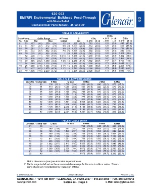
630-003
                  EMI/RFI  Environmental  Bulkhead  Feed-Through
                                        with Strain Relief                                                            63
                          Front and Rear Panel Mount -  45° and 90°


                                                    TABLE III: CABLE ENTRY
                                                                                          D Dia
                DashClamp       Cable Range       A Thread       B           C Sq.    + .015  (+ .4)  E Dia
                 No.  Size   Min         Max       Unified      Dim      ± .010  (± .3)  - .000  (-.0)  ± .010  (± .3)
                 01   03  .157  (4.0)  .250  (6.4)   1/2 -28  .885  (22.5)  .593  (15.1)  .120  (3.0)  .515    (13.1)
                 03   04  .187  (4.7)  .312  (7.9)   5/8 -24  1.104  (28.0)  .812  (20.6)  .120  (3.0)  .640    (16.3)
                 05   06  .281  (7.1)  .437  (11.1)  3/4 -20  1.197  (30.4)  .906  (23.0)  .120  (3.0)  .765    (19.4)
                 07   08  .344  (8.7)  .562  (14.3)  7/8 -20  1.291  (32.8)  .968  (24.6)  .120  (3.0)  .890   (22.6)
                 09   10  .375  (9.5)  .625  (15.9)   1 -20  1.385  (35.2)  1.062  (27.0)  .120  (3.0)  1.015   (25.8)
                 11   12  .438  (11.1)  .750  (19.1)  1 3/16 -18  1.635  (41.5)  1.250  (31.8)  .120  (3.0)  1.202   (30.5)
                 13   16  .625  (15.9)  .937  (23.8)  1 7/16 -18  1.760  (44.7)  1.375  (34.9)  .147  (3.7)  1.452   (36.9)
                 15   20  .875  (22.2) 1.250  (31.8)  1 3/4 -18  2.010  (51.1)  1.562  (39.7)  .147  (3.7)  1.765   (44.8)
                 17   24  1.000  (25.4) 1.375  (34.9)  2 -18  2.260  (57.4)  1.750  (44.5)  .173  (4.4)  2.015   (51.2)
                 19   28  1.250  (31.8) 1.625  (41.3)  2 1/4 -16  2.510  (63.8)  1.938  (49.2)  .173  (4.4)  2.265   (57.5)
                 21   32  1.437  (36.5) 1.875  (47.6)  2 1/2 -16  2.781  (70.6)  2.188  (55.6)  .173  (4.4)  2.515   (63.9)
                 23   40  1.875  (47.6) 2.250  (57.2)  3 -16  3.281  (83.3)  2.625  (66.7)  .173  (4.4)  3.015   (76.6)


                                                TABLE IV: ELBOW DIMENSIONS
                      Dash No. Clamp Size  F Max         G Max        H Max        J Max       K Max
                         01       03     .750  (19.1)  1.000  (25.4)  .639  (16.2)  .890  (22.6)  .670  (17.0)
                         03       04     .810  (20.6)  1.060  (26.9)  .664  (16.9)  .920  (23.4)  .670  (17.0)
                         05       06     .870  (22.1)  1.125  (28.6)  .688  (17.5)  .940  (23.9)  .670  (17.0)
                         07       08     .920  (23.4)  1.190  (30.2)  .705  (17.9)  .970  (24.6)  .670  (17.0)
                         09       10     .980  (24.9)  1.250  (31.8)  .732  (18.6)  .990  (25.1)  .670  (17.0)
                         11       12    1.080  (27.4)  1.330  (33.8)  .773  (19.6)  1.020  (25.9)  .670  (17.0)
                         13       16    1.200  (30.5)  1.480  (37.6)  .823  (20.9)  1.090  (27.7)  .670  (17.0)
                         15       20    1.480  (37.6)  1.781  (45.2)  1.041  (26.4)  1.322  (33.6)  .700  (17.8)
                         17       24    1.610  (40.9)  1.938  (49.2)  1.092  (27.7)  1.425  (36.2)  .700  (17.8)
                         19       28    1.720  (43.7)  2.045  (51.9)  1.138  (28.9)  1.475  (37.5)  .700  (17.8)
                         21       32    1.830  (46.5)  2.218  (56.3)  1.184  (30.1)  1.578  (40.1)  .820  (20.8)
                         23       40    2.080  (52.8)  2.594  (65.9)  1.287  (32.7)  1.802  (45.8)  .820  (20.8)


                                                    TABLE V: CABLE ENTRY
                      Dash No. Clamp Size  L Max         M Max        N Max        P Max       R Max
                         01       03      ---  ---      ---  ---    .760  (19.3)  .843  (21.4)  .630  (16.0)
                         03       04     .780  (19.8)  .957  (24.3)  .760  (19.3)  .906  (23.0)  .755  (19.2)
                         05       06     .780  (19.8)  1.145  (29.1)  .760  (19.3)  1.093  (27.8)  .942  (23.9)
                         07       08     .780  (19.8)  1.332  (33.8)  .760  (19.3)  1.187  (30.1)  1.067  (27.1)
                         09       10     .780  (19.8)  1.332  (33.8)  .760  (19.3)  1.281  (32.5)  1.192  (30.3)
                         11       12     .811  (20.6)  1.551  (39.4)  .760  (19.3)  1.500  (38.1)  1.380  (35.1)
                         13       16     .905  (23.0)  1.770  (45.0)  1.073  (27.3)  1.719  (43.7)  1.535  (39.0)
                         15       20    1.092  (27.7)  2.113  (53.7)  1.323  (33.6)  2.062  (52.4)  1.848  (46.9)
                         17       24    1.124  (28.5)  2.363  (60.0)  1.323  (33.6)  2.312  (58.7)  2.255  (57.3)
                         19       28    1.399  (35.5)  2.770  (70.4)  1.572  (39.9)  2.719  (69.1)  2.505  (63.6)
                         21       32    1.399  (35.5)  3.020  (76.7)  1.572  (39.9)  2.969  (75.4)  2.755  (70.0)
                         23       40      ---  ---      ---  ---   1.572  (39.9)  3.531  (89.7)  3.255  (82.7)


                     1. Metric dimensions (mm) are indicated in parentheses.
                     2. Cable range is defined as the accommodations range for the wire bundle or cable.  Dimen-
                       sions shown are not intended for inspection criteria.


               © 2005 Glenair, Inc.                      CAGE Code 06324                             Printed in U.S.A.
               GLENAIR, INC. • 1211 AIR WAY • GLENDALE, CA 91201-2497 • 818-247-6000 • FAX 818-500-9912
               www.glenair.com                        Series 63 -  Page 3               E-Mail: sales@glenair.com