
Page 533 - Circular Connector Backshells and Accessories
P. 533
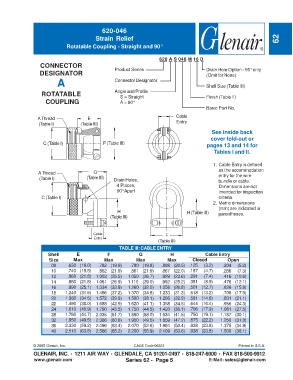
620-046
                                         Strain Relief                                                               62
                             Rotatable Coupling - Straight and 90°


                                                                    620 A S 046 M 16 D
                  CONNECTOR
                  DESIGNATOR                     Product Series                        Drain Hole Option - 90° only
                                                                                       (Omit for None)
                         A                       Connector Designator                  Shell Size (Table III)


                  ROTATABLE                      Angle and Profile                     Finish (Table II)
                                                   S = Straight
                    COUPLING                       A = 90°
                                                                                       Basic Part No.
                 A Thread             E                                    Cable
                 (Table I)         (Table III)                             Entry
                                                                                         See inside back
                                                                                         cover fold-out or
                   C (Table I)              F (Table III)                              pages 13 and 14 for
                                                                                          Tables I and II.

                                                                                          1. Cable Entry is defined
                 A Thread               G                                                   as the accommodation
                                                                                            entry for the wire
                 (Table I)           (Table III)  Drain Holes,                              bundle or cable.
                                                  4 Places,                                 Dimensions are not
                                                  90° Apart                                 intended for inspection
                  C (Table I)                                                               criteria.
                                                                                          2. Metric dimensions
                                                                                            (mm) are indicated in
                                                  H                            H (Table III)  parentheses.
                                               (Table III)


                                        Cable                         F
                                        Entry
                                                                   (Table III)
                                                   TABLE III: CABLE ENTRY
                     Shell       E            F            G            H              Cable Entry
                      Size      Max          Max          Max          Max       Closed         Open
                      08     .630 (16.0)  .782 (19.9)  .780 (19.8)  .808 (20.5)  .125  (3.2)  .204  (5.2)
                      10     .740 (18.8)  .862 (21.9)  .861 (21.9)  .867 (22.0)  .187  (4.7)  .286  (7.3)
                      12     .860 (21.8)  1.003 (25.5)  1.050 (26.7)  .929 (23.6)  .291  (7.4)  .416 (10.6)
                      14     .860 (21.8)  1.061 (26.9)  1.110 (29.0)  .992 (25.2)  .351  (8.9)  .476 (12.1)
                      16     .990 (25.1)  1.334 (33.9)  1.260 (32.0)  1.056 (26.8)  .501 (12.7)  .626 (15.9)
                      18    1.240 (31.5)  1.466 (37.2)  1.370 (34.8)  1.233 (31.3)  .518 (13.2)  .706 (17.9)
                      20    1.360 (34.5)  1.572 (39.9)  1.500 (38.1)  1.296 (32.9)  .581 (14.8)  .831 (21.1)
                      22    1.490 (38.0)  1.688 (42.9)  1.620 (41.1)  1.358 (34.5)  .644 (16.4)  .956 (24.3)
                      24    1.610 (40.9)  1.790 (45.5)  1.750 (44.5)  1.420 (36.1)  .706 (17.9)  1.081 (27.5)
                      28    1.760 (44.7)  2.035 (51.7)  1.890 (58.0)  1.634 (41.5)  .750 (19.1)  1.187 (30.1)
                      32    1.950 (49.5)  2.386 (60.6)  1.950 (49.5)  1.859 (47.2)  .875 (22.2)  1.250 (31.8)
                      36    2.330 (59.2)  2.496 (63.4)  2.070 (52.6)  1.984 (50.4)  .938 (23.8)  1.375 (34.9)
                      40    2.510 (63.8)  2.566 (65.2)  2.200 (55.9)  2.109 (53.6)  .938 (23.8)  1.500 (38.1)


               © 2005 Glenair, Inc.                      CAGE Code 06324                             Printed in U.S.A.
               GLENAIR, INC. • 1211 AIR WAY • GLENDALE, CA 91201-2497 • 818-247-6000 • FAX 818-500-9912
               www.glenair.com                        Series 62 -  Page 5               E-Mail: sales@glenair.com