
Page 351 - Circular Connector Backshells and Accessories
P. 351
Series 40
TAG Ring Backshells 40
®
Assembly Instructions
ASSEMBLY INSTRUCTIONS 40-1
The following suggested procedure serves as a guide for
®
proper assembly and installation of Glenair TAG Ring Back-
shells. Actual termination and assembly methods will de-
pend on the accepted techniques of the user. It is recom-
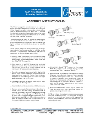
mended that trial samples of appropriate cables or harnesses TAG Ring Nut (2)
be used to determine proper trim dimensions of the conduc- Backshell (1)
tor shields and individual conductors.
Connector
These instructions are based on using a self-pigtailing tech-
nique for the individual shields, with the location at which the
conductors are extracted through the shields to be determined
by the particular connector involved, as well as backshell Strain Relief (3)
length.
Solder sleeves and ground wires may be used as an alter-
nate method of commonly grounding the individual conduc-
tor shields. A slight alteration of the following instructions will
permit easy termination of these ground wires.
a. Measure length of backshell (1) and determine length of
conductor needed to terminate to connector and locate FIGURE 1
shield pigtails approximately adjacent to the slotted por-
®
tion of the TAG Ring backshell.
FIGURE 2
b. Place backshell (1) and TAG Ring nut (2) or strain relief
®
(3) on wire bundle. Keep these components at a conve- ®
nient distance from the end of the wire bundle so they will g. With shields in place in TAG Ring backshell slots, engage
®
not interfere with subsequent assembly steps. TAG Ring nut (2) or strain relief (3), aligning grounding
spring tabs with slots. Tighten nut securely.
c. If shielded conductors have an outer jacket, strip jacket to
desired length. Extract conductors through shield at loca- h. Exposed shields may be trimmed flush with surface of TAG ®
tions determined in step (a). Flatten shield pigtails and Ring nut or strain relief body. However, if future repairabil-
temporarily tie pigtails flat against wire bundle, with pigtail ity is desired, it is suggested that at least 1 to 2 inches (25
ends facing away from the connector. to 50 mm) of extra shield length be preserved. Simply lay
the flattened shields against surface of the TAG Ring nut
®
d. Prepare and terminate conductors to connector in accor- and tie behind the nut against wire bundle as in Figure 2. If
dance with established practices. strain relief (3) is used, shield ends can be held in position
under strain relief saddles.
e. Assemble backshell (1) to connector and tighten securely.
j. If desired, heat shrinkable sleeving may be installed over
f. Remove temporary tie from pigtails and flare flattened TAG Ring nut to hold shields in place and to serve as a
®
shields outward from wire bundle. Distribute shields as protective covering and strain relief.
uniformly as possible among TAG Ring backshell slots as
®
shown in Figure 1. Grounding spring in TAG Ring nut (2) NOTE: As with any electrical connector assembly procedure,
®
or strain relief (3) compensates for differences in shield be sure to use the proper tools. For convenient, reliable as-
thickness of at least .020 inch (0.5 mm) between adjacent sembly of the connector and backshell, it is suggested that
slots. If necessary, double back shields to achieve uni- Glenair's connector holding tools, strap wrenches and con-
form shield thickness between adjacent slots. nector pliers be used.
© 2005 Glenair, Inc. CAGE Code 06324 Printed in U.S.A.
GLENAIR, INC. • 1211 AIR WAY • GLENDALE, CA 91201-2497 • 818-247-6000 • FAX 818-500-9912
www.glenair.com Series 40 - Page 3 E-Mail: sales@glenair.com