
Page 327 - Circular Connector Backshells and Accessories
P. 327
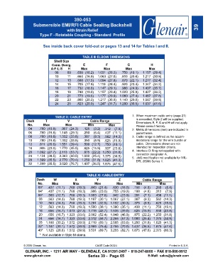
390-053
                     Submersible EMI/RFI Cable Sealing Backshell
                                        with Strain Relief                                                            39
                        Type F - Rotatable Coupling - Standard  Profile


                          See inside back cover fold-out or pages 13 and 14 for Tables I and II.


                                                  TABLE III:ELBOW DIMENSIONS
                                 Shell Size
                                Conn  Desig.      E            F            G             H
                               A-F-L-S   H       Max          Max          Max           Max
                                 08      09   .639 (16.2)  1.031 (26.2)  .750 (19.1)  1.157 (29.4)
                                 10      11   .664 (16.9)  1.063 (27.0)  .810 (20.6)  1.217 (30.9)
                                 12      13   .688 (17.5)  1.094 (27.8)  .870 (22.1)  1.277 (32.4)
                                 14      15   .705 (17.9)  1.119 (28.4)  .920 (23.4)  1.347 (34.2)
                                 16      17   .732 (18.6)  1.147 (29.1)  .980 (24.9)  1.407 (35.7)
                                 18      19   .748 (19.0)  1.157 (29.4) 1.020 (25.9)  1.427 (36.2)
                                 20      21   .773 (19.6)  1.177 (29.9) 1.080 (27.4)  1.487 (37.8)
                                 22      23   .800 (20.3)  1.217 (30.9) 1.140 (29.0)  1.567 (39.8)
                                 24      25   .823 (20.9)  1.247 (31.7) 1.200 (30.5)  1.637 (41.6)


                                  TABLE X: CABLE ENTRY                         1. When maximum cable entry (page 21)
                 Dash       T            V            Cable Range                is exceeded, Style 2 will be supplied.
                 No.       Max          Max          Min         Max             Dimensions E, F, G and H will not apply.
                                                                                 Please consult factory.
                  04    .780 (19.8)  .957 (24.3)  .125  (3.2)  .312  (7.9)     2. Metric dimensions (mm) are indicated in
                  06    .780 (19.8)  1.145 (29.1)  .250  (6.4)  .437 (11.1)      parentheses.
                  08    .780 (19.8)  1.332 (33.8)  .387  (9.3)  .562 (14.3)    3. Cable range is defined as the accom-
                  10    .780 (19.8)  1.332 (33.8)  .350  (8.9)  .625 (15.9)      modations range for the wire bundle or
                  12    .811 (20.6)  1.551 (39.4)  .500 (12.7)  .750 (19.1)      cable.  Dimensions shown are not
                  16    .905 (23.0)  1.770 (45.0)  .625 (15.9)  .937 (23.8)      intended for inspection criteria.
                  20   1.092 (27.7)  2.113 (53.7)  .875 (22.2) 1.250 (31.8)    4. Interface O-Ring not supplied with
                  24   1.124 (28.5)  2.363 (60.0)  1.000 (25.4) 1.375 (34.9)     connector designator A.
                  28   1.399 (35.5)  2.770 (70.4)  1.250 (31.8) 1.625 (41.3)   5.  -445 modification not available for MIL-
                                                                                 DTL-38999 Series II.
                  32   1.399 (35.5)  3.020 (76.7)  1.437 (36.5) 1.875 (47.6)

                                                    TABLE XI: CABLE ENTRY
                       Dash      W           X            Y            Z             Cable Range
                       No.      Max         Max          Max          Max        Min           Max
                        03*  .437 (11.1)  .760 (19.3)  .843 (21.4)  .630 (16.0)  .156  (4.0)  .250  (6.4)
                        04*  .437 (11.1)  .760 (19.3)  .906 (23.0)  .755 (19.2)  .188  (4.8)  .312  (7.9)
                        06*  .500 (12.7)  .760 (19.3) 1.093 (27.8)  .942 (23.9)  .281  (7.1)  .438 (11.1)
                        08   .563 (14.3)  .760 (19.3) 1.187 (30.1)  1.067 (27.1)  .387  (9.3)  .562 (14.3)
                        10   .563 (14.3)  .760 (19.3) 1.281 (32.5)  1.192 (30.3)  .375  (9.5)  .625 (15.9)
                        12   .563 (14.3)  .760 (19.3) 1.500 (38.1)  1.380 (35.1)  .438 (11.1)  .750 (19.1)
                        16   .656 (16.7)  1.073 (27.3) 1.719 (43.7)  1.535 (39.0)  .625 (15.9)  .938 (23.8)
                        20   .656 (16.7)  1.323 (33.6) 2.062 (52.4)  1.848 (46.9)  .875 (22.2)  1.250 (31.8)
                        24   .656 (16.7)  1.323 (33.6) 2.312 (58.7)  2.255 (57.3) 1.000 (25.4)  1.375 (34.9)
                        28  1.188 (30.2)  1.572 (39.9) 2.719 (69.1)  2.505 (63.6) 1.250 (31.8)  1.625 (41.3)
                        32* 1.187 (30.1)  1.572 (39.9) 2.969 (75.4)  2.755 (70.0) 1.437 (36.5)  1.875 (47.6)
                        40* 1.125 (28.6)  1.572 (39.9) 3.531 (89.7)  3.255 (82.7) 1.875 (47.6)  2.375 (60.3)
                        *  Not available in Style M clamp.


               © 2005 Glenair, Inc.                      CAGE Code 06324                             Printed in U.S.A.
                GLENA  INC. • 1211 AIR WAY •  GLENDA    91201-2497 •  818-247-6000 •  FA  818-500-9912
               www.glenair.com                       Series 39 -  Page 65                 sales@glenair.com