
Page 329 - Circular Connector Backshells and Accessories
P. 329
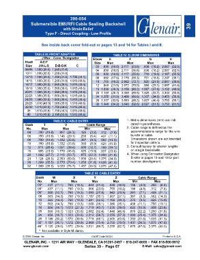
390-054
                    Submersible EMI/RFI Cable Sealing Backshell
                                        with Strain Relief                                                            39
                             Type F - Direct Coupling - Low Profile


                          See inside back cover fold-out or pages 13 and 14 for Tables I and II.


                      TABLE III: FRONT ADAPTER                        TABLE IV: ELBOW DIMENSIONS
                           J Max - Conn. Designator       Elbow     E           F           G            H
                Shell     A-E-F                            Size   Max          Max         Max          Max
                 Size    J-H-L-S   D-B-G-K      C           03  .630 (16.0) 2.117 (53.8)  .636 (16.2) 2.067 (52.5)
                08/09 1.180(30.0) 1.250(31.8)               04  .630 (16.0) 2.117 (35.8)  .636 (16.2) 2.067 (52.5)
                10/11 1.180(30.0) 1.250(31.8)               06  .630 (16.0) 2.117 (35.8)  .710 (18.0) 2.187 (55.5)
                12/13 1.180(30.0) 1.250(31.8) 1.735(44.1)   08  .692 (17.6) 2.179 (55.3)  .731 (18.6) 2.207 (39.1)
                14/15 1.180(30.0) 1.250(31.8) 1.915(48.6)   10  .755 (19.2) 2.862 (72.7)  .825 (21.0) 2.867 (39.6)
                16/17 1.380(35.0) 1.560(39.6) 1.915(48.6)   12  .848 (21.5) 2.972 (75.5)  .988 (25.1) 2.957 (41.4)
                18/19 1.380(35.0) 1.560(39.6) 1.915(48.6)   16  1.036 (26.3) 3.159 (80.2)  1.087 (27.6) 3.132 (48.0)
                20/21 1.380(35.0) 1.560(39.6) 1.915(48.6)   20  1.130 (28.7) 3.368 (85.5)  1.325 (33.7) 3.303 (50.8)
                22/23 1.380(35.0) 1.560(39.6) 1.915(48.6)   24  1.255 (31.9) 3.408 (86.6)  1.337 (34.0) 3.453 (50.8)
                24/25 1.380(35.0) 1.560(39.6) 1.915(48.6)   28  1.317 (33.5) 3.553 (90.2)  1.827 (46.4) 3.703 (55.1)
                28/29 1.610 (40.9) 1.560(39.6) 1.915(48.6)  32  1.348 (34.2) 3.646 (92.6)  2.027 (51.5) 3.753 (61.5)
                32/33 1.610(40.9) 1.750(44.5) 1.915(48.6)
                  36  1.610(40.9) 1.750(44.5) 1.915(48.6)
                  40  1.610(40.9) 2.190(55.6) 1.915(48.6)
                                  TABLE X: CABLE ENTRY                         1. Metric dimensions (mm) are indi-
                 Dash       T            V            Cable Range                cated in parentheses.
                 No.       Max          Max          Min         Max           2. Cable range is defined as the
                  04    .780 (19.8)  .957 (24.3)  .125  (3.2)  .312  (7.9)       accommodations range for the wire
                  06    .780 (19.8)  1.145 (29.1)  .250  (6.4)  .437 (11.1)      bundle or cable.
                  08    .780 (19.8)  1.332 (33.8)  .387  (9.3)  .562 (14.3)      Dimensions shown are not intended
                  10    .780 (19.8)  1.332 (33.8)  .350  (8.9)  .625 (15.9)      for inspection criteria.
                  12    .811 (20.6)  1.551 (39.4)  .500 (12.7)  .750 (19.1)    3. Consult factory for shorter lengths
                  16    .905 (23.0)  1.770 (45.0)  .625 (15.9)  .937 (23.8)      on staight backshells.
                  20   1.092 (27.7)  2.113 (53.7)  .875 (22.2) 1.250 (31.8)    4. When using Connector Designator
                  24   1.124 (28.5)  2.363 (60.0)  1.000 (25.4) 1.375 (34.9)     B refer to pages 18 and 19 for part
                  28   1.399 (35.5)  2.770 (70.4)  1.250 (31.8) 1.625 (41.3)     number development.
                  32   1.399 (35.5)  3.020 (76.7)  1.437 (36.5) 1.875 (47.6)

                                                     TABLE XI: CABLE ENTRY
                       Dash      W            X            Y            Z             Cable Range
                        No.     Max          Max         Max          Max         Min           Max
                        03*   .437 (11.1)  .760 (19.3)  .843 (21.4)  .630 (16.0)  .156  (4.0)  .250  (6.4)
                        04*   .437 (11.1)  .760 (19.3)  .906 (23.0)  .755 (19.2)  .188  (4.8)  .312  (7.9)
                        06*   .500 (12.7)  .760 (19.3) 1.093 (27.8)  .942 (23.9)  .281  (7.1)  .438 (11.1)
                         08   .563 (14.3)  .760 (19.3) 1.187 (30.1)  1.067 (27.1)  .387  (9.3)  .562 (14.3)
                         10   .563 (14.3)  .760 (19.3) 1.281 (32.5)  1.192 (30.3)  .375  (9.5)  .625 (15.9)
                         12   .563 (14.3)  .760 (19.3) 1.500 (38.1)  1.380 (35.1)  .438 (11.1)  .750 (19.1)
                         16   .656 (16.7)  1.073 (27.3) 1.719 (43.7)  1.535 (39.0)  .625 (15.9)  .938 (23.8)
                         20   .656 (16.7)  1.323 (33.6) 2.062 (52.4)  1.848 (46.9)  .875 (22.2)  1.250 (31.8)
                         24   .656 (16.7)  1.323 (33.6) 2.312 (58.7)  2.255 (57.3) 1.000 (25.4)  1.375 (34.9)
                         28  1.188 (30.2)  1.572 (39.9) 2.719 (69.1)  2.505 (63.6) 1.250 (31.8)  1.625 (41.3)
                        32* 1.187 (30.1)  1.572 (39.9) 2.969 (75.4)  2.755 (70.0) 1.437 (36.5)  1.875 (47.6)
                        40* 1.125 (28.6)  1.572 (39.9) 3.531 (89.7)  3.255 (82.7) 1.875 (47.6)  2.375 (60.3)
                         *  Not available in Style M clamp.
               © 2005 Glenair, Inc.                      CAGE Code 06324                             Printed in U.S.A.
                GLENA  INC. • 1211 AIR WAY •  GLENDA    91201-2497 •  818-247-6000 •  FA  818-500-9912
               www.glenair.com                       Series 39 -  Page 67                 sales@glenair.com