
Page 563 - Circular Connector Backshells and Accessories
P. 563
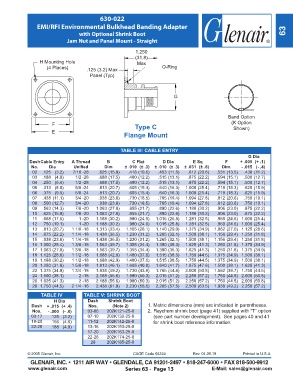
630-022
                 EMI/RFI Environmental Bulkhead Banding Adapter
                                  with Optional Shrink Boot                                                             63
                             Jam Nut and Panel Mount - Straight

                                                          1.250
                                                          (31.8)
                  H Mounting Hole                         Max
                     (4 Places)      .125 (3.2) Max                  O-Ring
                                       Panel (Typ)


                                                                          G


                                                                                                Band Option
                       F                                 Type C                                   (K Option
                       E                                                                           Shown)
                                                     Flange Mount

                                                   TABLE III: CABLE ENTRY
                                                                                                         G Dia
             Dash Cable Entry  A Thread       B         C Flat       D Dia        E Sq         F      + .005  (+ .1)
              No.     Dia       Unified      Dim      ± .010  (± .3)   ± .010  (± .3)   ± .031  (± .8)  Dim.    - .015  (- .4)
                  02  .125   (3.2)    7/16 -28     .625 (15.9)    .418 (10.6)    .453  (11.5)    .812 (20.6)   .531 (13.5)    .438  (11.2)
                  03  .188   (4.8)     1/2 -28     .688  (17.5)    .480  (12.2)    .515  (13.1)    .875  (22.2)    .594  (15.1)     .500  (12.7)
                  04  .250   (6.4)     1/2 -28     .688  (17.5)    .480  (12.2)    .515  (13.1)    .875  (22.2)    .594  (15.1)     .500  (12.7)
                  05  .313   (8.0)     5/8 -24     .813  (20.7)    .605  (15.4)    .640  (16.3)   1.000  (25.4)    .719  (18.3)     .625  (15.9)
                  06  .375   (9.5)     5/8 -24     .813  (20.7)    .605  (15.4)    .640  (16.3)   1.000  (25.4)    .719  (18.3)     .625  (15.9)
                  07  .438  (11.1)     3/4 -20     .938  (23.8)    .730  (18.5)    .765  (19.4)   1.094  (27.8)    .812  (20.6)     .750  (19.1)
                  08  .500  (12.7)     3/4 -20     .938  (23.8)    .730  (18.5)    .765  (19.4)   1.094  (27.8)    .812  (20.6)     .750  (19.1)
                  09  .563  (14.3)     7/8 -20    1.063  (27.0)    .855  (21.7)    .890  (22.6)   1.188  (30.2)    .906  (23.0)     .875  (22.2)
                  10  .625  (15.9)     7/8 -20    1.063  (27.0)    .855  (21.7)    .890  (22.6)   1.188  (30.2)    .906  (23.0)     .875  (22.2)
                  11  .688  (17.5)     1 -20    1.188  (30.2)    .980  (24.9)   1.015  (25.8)   1.281  (32.5)    .969  (24.6)    1.000  (25.4)
                  12  .750  (19.1)     1 -20    1.188  (30.2)    .980  (24.9)   1.015  (25.8)   1.281  (32.5)    .969  (24.6)    1.000  (25.4)
                  13  .813  (20.7)    1 1/8 -18    1.313  (33.4)   1.105  (28.1)   1.140  (29.0)   1.375  (34.9)   1.062  (27.0)    1.125  (28.6)
                  14  .875  (22.2)    1 1/4 -18    1.438  (36.5)   1.230  (31.2)   1.265  (32.1)   1.500  (38.1)   1.156  (29.4)    1.250  (31.8)
                  15  .938  (23.8)    1 1/4 -18    1.438  (36.5)   1.230  (31.2)   1.265  (32.1)   1.500  (38.1)   1.156  (29.4)    1.250  (31.8)
                  1.000  (25.4)    1 3/8 -18
               16                        1.563  (39.7)   1.355  (34.4)   1.390  (35.3)   1.625  (41.3)   1.250  (31.8)    1.375  (34.9)
               17                        1.563  (39.7)   1.355  (34.4)   1.390  (35.3)   1.625  (41.3)   1.250  (31.8)    1.375  (34.9)
                  1.063  (27.0)    1 3/8 -18
               18                        1.688  (42.9)   1.480  (37.6)   1.515  (38.5)   1.750  (44.5)   1.375  (34.9)    1.500  (38.1)
                  1.125  (28.6)    1 1/2 -18
               19                        1.688  (42.9)   1.480  (37.6)   1.515  (38.5)   1.750  (44.5)   1.375  (34.9)    1.500  (38.1)
                  1.188  (30.2)    1 1/2 -18
               20                        1.813  (46.1)   1.605  (40.8)   1.640  (41.7)   1.875  (47.6)   1.500  (38.1)    1.625  (41.3)
                  1.250  (31.8)    1 5/8 -18
               22                        1.938  (49.2)   1.730  (43.9)   1.765  (44.8)   2.000  (50.8)   1.562  (39.7)    1.750  (44.5)
                  1.375  (34.9)    1 3/4 -18
                  1.500  (38.1)
               24                 2 -18    2.188  (55.6)   1.980  (50.3)   2.015  (51.2)   2.250  (57.2)   1.750  (44.5)    2.000  (50.8)
               26                 2 -18    2.188  (55.6)   1.980  (50.3)   2.015  (51.2)   2.250  (57.2)   1.750  (44.5)    2.000  (50.8)
                  1.625  (41.3)
                  1.750  (44.5)    2 1/4 -16
               28                        2.438  (61.9)   2.230  (56.6)   2.265  (57.5)   2.500  (63.5)   1.938  (49.2)    2.250  (57.2)
                  TABLE IV          TABLE V: SHRINK BOOT
                        H Dia         Dash    Shrink Boot
              Dash   + .015  (+ .4)   Nos.      (Note 2)       1. Metric dimensions (mm) are indicated in parentheses.
              Nos.   - .000  (- .0)   03-06    202K121-25-0    2. Raychem shrink boot (page 41) supplied with "T" option
              03-17    .125   (3.2)   07-10   202K132-25-0       (see part number development).  See pages 40 and 41
              18-20    .156   (4.0)   11-12   202K142-25-0       for shrink boot reference information.
              22-28    .188   (4.8)   13-16   202K153-25-0
                                      17-20   202K163-25-0
                                      22-26   202K174-25-0
                                       28     202K185-25-0
             © 2005 Glenair, Inc.                        CAGE Code 06324          Rev. 04.06.18        Printed in U.S.A.
              GLENAIR, INC. • 1211 AIR WAY • GLENDALE, CA 91201-2497 • 818-247-6000 • FAX 818-500-9912
             www.glenair.com                         Series 63 -  Page 13                 E-Mail: sales@glenair.com