
Page 514 - Circular Connector Backshells and Accessories
P. 514
Series 460
Non-Environmental EMI/RFI G-Spring Backshells
Assembly Instructions
460
ASSEMBLY INSTRUCTIONS 460-1
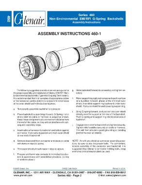
The following suggested procedure serves as a guide for g. Slide backshell forward to connector, and tighten se-
the proper assembly and installation of Glenair EMI/RFI Non- curely.
Environmental Backshells (Type 460 G-spring Termination).
It is recommended that trial samples of appropriate cables h. Move support ring (optional component used over lose
or harnesses be used to determine proper trim dimensions wire bundles) forward, ahead of the trimmed outer
of the outer shield and individual conductors. shield, then slide support ring backward under outer
shield. Pull outer shield forward covering support ring.
a. Temporarily assemble backshell to connector.
i. Bring G-spring forward, and position on outer shield
b. Place backshell, support ring (if used), G-Spring, nut or directly over the support at the rear of the backshell.
strain relief on cable or harness in sequence shown. Push G-spring and support ring into beveled area of
Keep these components at a convenient distance from backshell.
the end of the cable, so they will not interfere with sub-
sequent assembly steps. j. Engage strain relief to backshell and tighten securely.
Tighten relief saddles securely on cable or harness.
c. Insert cable or harness into backshell and bottom against This will then provide a good grounding or bonding
connector. Hold cable in position and mark outer shield joint for the over-all shields.
at rear end of backshell.
d. Remove backshell from connector and place on cable NOTE: As with any electrical connector assembly proce-
with items in step (b) above. dure, be sure to use the proper tools. For convenient,
reliable assembly of the connector and backshell, it is
e. Trim outer shield at mark made in step (c) above. suggested that Glenair’s connector holding tools, strap
wrenches and connector pliers be used.
f. Prepare and terminate contacts to individual conduc-
tors in accordance with established practices. (Crimp
or solder in place.)
© 2005 Glenair, Inc. CAGE Code 06324 Printed in U.S.A.
GLENAIR, INC. • 1211 AIR WAY • GLENDALE, CA 91201-2497 • 818-247-6000 • FAX 818-500-9912
www.glenair.com Series 460 - Page 2 E-Mail: sales@glenair.com