
Page 509 - Circular Connector Backshells and Accessories
P. 509
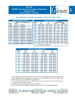
463-002
                     EMI/RFI  Environmental  G-Spring  Backshell
                                        with Strain Relief                                                            463
                                 Direct Coupling - Low Profile


                           See inside back cover fold-out or pages 13 and 14 for Tables I and II.


                      TABLE III: FRONT ADAPTER                           TABLE IV: CABLE ENTRY
                          J Max - Conn. Designator       Dash      M            N            Cable Range
                Shell    A-E-F                            No.     Max         Max          Min         Max
                 Size   J-H-L-S   D-B-G-K      C          01    .843 (21.4)  .625 (15.9)  .125  (3.2)  .250  (6.4)
                08/09 1.180(30.0) 1.440(36.6)             02    .968 (24.6)  .750 (19.1)  .156  (4.0)  .375  (9.5)
                10/11 1.180(30.0) 1.440(36.6)             03   1.046 (26.6)  .875 (22.2)  .250  (6.4)  .438 (11.1)
                12/13 1.180(30.0) 1.440(36.6) 1.735(44.1)  04  1.156 (29.4) 1.000 (25.4)  .280  (7.1)  .500 (12.7)
                14/15 1.180(30.0) 1.440(36.6) 1.915(48.6)  05  1.218 (30.9) 1.125 (28.6)  .375  (9.5)  .625 (15.9)
                16/17 1.380(35.0) 1.560(39.6) 1.915(48.6)  06  1.343 (34.1) 1.250 (31.8)  .500 (12.7)  .750 (19.1)
                18/19 1.380(35.0) 1.560(39.6) 1.915(48.6)  07  1.468 (37.3) 1.375 (34.9)  .625 (15.9)  .875 (22.2)
                20/21 1.380(35.0) 1.560(39.6) 1.915(48.6)  08  1.593 (40.5) 1.500 (38.1)  .750 (19.1) 1.000 (25.4)
                22/23 1.380(35.0) 1.560(39.6) 1.915(48.6)  09  1.718 (43.6) 1.625 (41.3)  .875 (22.2) 1.125 (28.6)
                24/25 1.380(35.0) 1.560(39.6) 1.915(48.6)  10  1.843 (46.8) 1.750 (44.5)  1.000 (25.4) 1.250 (31.8)
                28/29 1.610 (40.9) 1.560(39.6) 1.915(48.6)  11*  2.187 (55.5) 1.875 (47.6)  1.125 (28.6) 1.375 (34.9)
                32/33 1.610(40.9) 1.750(44.5) 1.915(48.6)  12*  2.312 (58.7) 2.000 (50.8)  1.250 (31.8) 1.500 (38.1)
                 36   1.610(40.9) 1.750(44.5) 1.915(48.6)  13*  2.437 (61.9) 2.125 (54.0)  1.375 (34.9) 1.625 (41.3)
                 40   1.610(40.9) 2.190(55.6) 1.915(48.6)  14*  2.546 (64.7) 2.250 (57.2)  1.500 (38.1) 1.750 (44.5)
                                                          *  Consult factory for availability


                                               TABLE V: ELBOW DIMENSIONS
                             Elbow         E             F             G              H
                              Size       Max            Max           Max            Max
                               01      .630 (16.0)  1.720 (43.7)    .636 (16.2)  1.670 (42.4)
                               02      .630 (16.0)  1.720 (43.7)    .710 (18.0)  1.790 (45.5)
                               03      .692 (17.6)  1.780 (45.2)    .734 (18.6)  1.810 (46.0)
                               04      .755 (19.2)  1.870 (47.5)    .825 (21.0)  1.880 (47.8)
                               05      .848 (21.5)  1.980 (50.3)    .988 (25.1)  1.970 (50.0)
                               06     1.036 (26.3)  2.170 (55.1)   1.087 (27.6)  2.140 (54.4)
                               07     1.036 (26.3)  2.170 (55.1)   1.087 (27.6)  2.140 (54.4)
                               08     1.130 (28.7)  2.320 (58.9)   1.325 (33.7)  2.250 (57.2)
                               09     1.130 (28.7)  2.320 (58.9)   1.325 (33.7)  2.250 (57.2)
                               10     1.255 (31.9)  2.370 (60.2)   1.337 (34.0)  2.420 (61.5)
                               11     1.317 (33.5)  2.470 (62.7)   1.827 (46.4)  2.670 (67.8)
                               12     1.317 (33.5)  2.470 (62.7)   1.827 (46.4)  2.670 (67.8)
                               13     1.348 (34.2)  2.560 (65.0)   2.027 (51.5)  2.670 (67.8)
                               14     1.348 (34.2)  2.560 (65.0)   2.027 (51.5)  2.670 (67.8)


                  1. Shield Support Ring (469-001-XX) is recommended for use in all G-Spring backshells (see page 463-8).
                  2. When maximum cable entry (page 22) is exceeded, Style 2 will be supplied.  Angular Function S only.
                  3. Metric dimensions (mm) are indicated in parentheses.
                  4. Cable range is defined as the accommodations range for the wire bundle or cable.  Dimensions shown
                     are not intended for inspection criteria.
                  5. Consult factory for shorter lengths on straight backshells.
                  6. When using Connector Designator B refer to pages 18 and 19 for part number development.


               © 2005 Glenair, Inc.                      CAGE Code 06324                             Printed in U.S.A.
               GLENAIR, INC. • 1211 AIR WAY • GLENDALE, CA 91201-2497 • 818-247-6000 • FAX 818-500-9912
               www.glenair.com                       Series 463 -  Page 5               E-Mail: sales@glenair.com