
Page 403 - Circular Connector Backshells and Accessories
P. 403
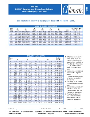
440-030

                      EMI/RFI Banding and Shrink Boot Adapter                                                           440
                               Rotatable Coupling - Split Shell


                        See inside back cover fold-out or pages 13 and 14  for Tables I and II.


                                                TABLE III: ELBOW DIMENSIONS
               Shell     E          F          G           H         J           K          L     Function C Max
               Size     Max        Max        Max         Max       Ref         Max        Max      Wire Bundle
               08/09    .440  (11.2)    1.635  (41.5)   .680 (17.3)    1.575  (40.0)    .340  (8.6)   .681 (17.3)    .250   (6.4)
                                                                            1.915  (48.6)

                                                                            2.075  (52.7)
               10/11    .500 (12.7)    1.695  (43.1)   .750 (19.1)    1.635  (41.5)    .270  (6.9)   .731 (18.6)    .375   (9.5)

                                                                            2.075  (52.7)

               12/13    .560 (14.2)    1.765  (44.8)   .810 (20.6)    1.705  (43.3)    .270  (6.9)   .731 (18.6)    .375   (9.5)
                                                                            2.145  (54.5)

               14/15    .620 (15.7)    1.795  (45.6)   .870 (22.1)    1.735  (44.1)    .280  (7.1)   .831 (21.1)    .500  (12.7)
               16/17    .680 (17.3)    1.895  (48.1)   .930 (23.6)    1.835  (46.6)    .420 (10.7)   .981 (24.9)    .625  (15.9)

                                                                            2.195  (55.8)
                                          1.000 (25.4)    1.895  (48.1)
               18/19    .750 (19.1)    1.955  (49.7)              .640 (16.3)                        .625  (15.9)
                                                                            2.225  (56.5)    1.181 (30.0)
               20/21    .820 (20.8)    2.015  (51.2)              .640 (16.3)                        .625  (15.9)
                                                                            2.225  (56.5)    1.181 (30.0)
                                          1.060 (26.9)    1.955  (49.7)
                                          1.120 (28.4)    2.015  (51.2)
                                                                            2.375  (60.3)    1.181 (30.0)
               22/23    .880 (22.4)    2.075  (52.7)              .540 (13.7)                        .750  (19.1)
                                          1.180 (30.0)    2.075  (52.7)
                                                                            2.375  (60.3)    1.181 (30.0)
               24/25    .940 (23.9)    2.135  (54.2)              .540 (13.7)                        .750  (19.1)
                                      TABLE IV: CABLE ENTRY                               1. When maximum cable
             Dash                                                            Shrink         entry (page 21) is ex-
              No.       M             N             P            R            Boot          ceeded, Style 2 will be
              01    .125  (3.2)     .125  (3.2)    .250  (6.4)     .312  (7.9)  770-003S111  supplied (not available in
              31    .170  (4.3)     .188  (4.8)    .312  (7.9)     .374  (9.5)  770-003S111  Function C).  Dimensions
              02    .170  (4.3)     .250  (6.4)    .375  (9.5)     .437  (11.1)  770-003S112  E, F, G, and H will not
              32    .170  (4.3)     .312  (7.9)    .438  (11.1)     .500  (12.7)  770-003S112  apply.  Please consult
              03    .250  (6.4)     .375  (9.5)    .500  (12.7)     .562  (14.3)  770-003S112  factory.
              33    .250  (6.4)     .438  (11.1)    .562  (14.3)     .624  (15.8)  770-001S104  2. Metric dimensions (mm)
              04    .250  (6.4)     .500  (12.7)    .625  (15.9)     .687  (17.4)  770-001S104  are indicated in paren-
              34    .250  (6.4)     .562  (14.3)    .688  (17.5)     .750  (19.1)  770-001S104  theses.
              05    .500  (12.7)     .625  (15.9)    .750  (19.1)     .812  (20.6)  770-001S104  3. Consult factory for short-
              35    .500  (12.7)     .688  (17.5)    .812  (20.6)     .874  (22.2)  770-001S104  er lengths on straight
              06    .500  (12.7)     .750  (19.1)    .875  (22.2)     .937  (23.8)  770-001S105  backshells.
              36    .500  (12.7)     .812  (20.6)    .938  (23.8)    1.000  (25.4)  770-001S105  4. See page 40 for Shrink
              07    .500  (12.7)     .875  (22.2)   1.000  (25.4)    1.062  (27.0)  770-001S105  Boot Reference Informa-
              37    .500  (12.7)     .938  (23.8)   1.062  (27.0)    1.124  (28.5)  770-001S105  tion.
              08    .500  (12.7)    1.000  (25.4)   1.125  (28.6)    1.187  (30.1)  770-001S106  5. Backshells supplied with
              38    .500  (12.7)    1.062  (27.0)   1.188  (30.2)    1.250  (31.8)  770-001S106  600-052-* band, see
              09    .500  (12.7)    1.125  (28.6)   1.250  (31.8)    1.312  (33.3)  770-001S107  Glenair Series 600 Tool
              10    .750  (19.1)    1.250  (31.8)   1.375  (34.9)    1.437  (36.5)  770-001S107  Catalog for installation.
               11    .750  (19.1)    1.375  (34.9)   1.500  (38.1)    1.562  (39.7)  770-001S107  6. Angular function “C”,
              12   1.000  (25.4)    1.500  (38.1)    1.625  (41.3)    1.687  (42.8)  770-001S107  low-profile split elbow,
              13   1.000  (25.4)    1.625  (41.3)   1.750  (44.5)    1.812  (46.0)  770-001S108  not available with “S”
              14   1.000  (25.4)    1.750  (44.5)   1.875  (47.6)    1.937  (49.2)  770-001S108  connector designator.
              15   1.000  (25.4)    1.875  (47.6)   2.000  (50.8)    2.062  (52.4)  770-001S109
              16   1.000  (25.4)    2.000  (50.8)   2.125  (54.0)    2.187  (55.5)  770-001S109


             © 2005 Glenair, Inc.                        CAGE Code 06324          Rev. 11.10.14        Printed in U.S.A.
              GLENAIR, INC. • 1211 AIR WAY • GLENDALE, CA 91201-2497 • 818-247-6000 • FAX 818-500-9912
             www.glenair.com                         Series 440 -  Page 17                E-Mail: sales@glenair.com