
Page 405 - Circular Connector Backshells and Accessories
P. 405
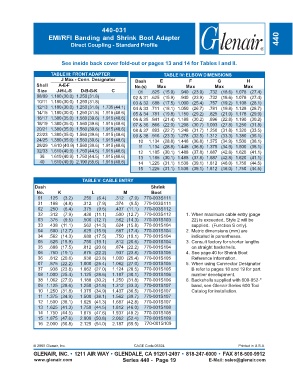
440-031
                     EMI/RFI Banding and Shrink Boot Adapter                                                         440
                               Direct Coupling - Standard Profile


                           See inside back cover fold-out or pages 13 and 14 for Tables I and II.
                      TABLE III: FRONT ADAPTER                       TABLE IV: ELBOW DIMENSIONS
                           J Max - Conn. Designator       Dash      E           F           G           H
                Shell    A-E-F                           No.(s)    Max         Max         Max         Max
                 Size    J-H-L-S   D-B-G-K      C          01   .625 (15.9)  .940 (23.9)  .732 (18.6)  1.078 (27.4)
                08/09 1.180 (30.0) 1.250 (31.8)          02 & 31  .625 (15.9)  .940 (23.9)  .732 (18.6)  1.078 (27.4)
                10/11 1.180 (30.0) 1.250 (31.8)          03 & 32  .688 (17.5) 1.000 (25.4)  .757 (19.2)  1.108 (28.1)
                12/13 1.180 (30.0) 1.250 (31.8) 1.735 (44.1)  04 & 33  .711 (18.1) 1.050 (26.7)  .781 (19.8)  1.128 (28.7)
                14/15 1.180 (30.0) 1.250 (31.8) 1.915 (48.6)  05 & 34  .781 (19.8) 1.150 (29.2)  .825 (21.0)  1.178 (29.9)
                16/17 1.380 (35.0) 1.560 (39.6) 1.915 (48.6)  06 & 35  .841 (21.4) 1.188 (30.2)  .896 (22.8)  1.190 (30.2)
                18/19 1.380 (35.0) 1.560 (39.6) 1.915 (48.6)  07 & 36  .866 (22.0) 1.208 (30.7) 1.093 (27.8)  1.250 (31.8)
                20/21 1.380 (35.0) 1.560 (39.6) 1.915 (48.6)  08 & 37  .893 (22.7) 1.248 (31.7) 1.250 (31.8)  1.320 (33.5)
                22/23 1.380 (35.0) 1.560 (39.6) 1.915 (48.6)  09 & 38  .916 (23.3) 1.278 (32.5) 1.312 (33.3)  1.380 (35.1)
                24/25 1.380 (35.0) 1.560 (39.6) 1.915 (48.6)  10  1.134 (28.8) 1.448 (36.8) 1.375 (34.9)  1.500 (38.1)
                28/29 1.610 (40.9) 1.560 (39.6) 1.915 (48.6)  11  1.134 (28.8) 1.448 (36.8) 1.375 (34.9)  1.500 (38.1)
                32/33 1.610 (40.9) 1.750 (44.5) 1.915 (48.6)  12  1.185 (30.1) 1.488 (37.8) 1.687 (42.8)  1.620 (41.1)
                  36  1.610 (40.9) 1.750 (44.5) 1.915 (48.6)  13  1.185 (30.1) 1.488 (37.8) 1.687 (42.8)  1.620 (41.1)
                  40  1.610 (40.9) 2.190 (55.6) 1.915 (48.6)  14  1.225 (31.1) 1.538 (39.1) 1.812 (46.0)  1.750 (44.5)
                                                           15  1.225 (31.1) 1.538 (39.1) 1.812 (46.0)  1.750 (44.5)

                                   TABLE V: CABLE ENTRY
                Dash                                            Shrink
                No.      K             L             M          Boot
                 01   .125  (3.2)   .250  (6.4)  .312  (7.9)  770-003S111
                 31   .188  (4.8)   .312  (7.9)  .374  (9.5)  770-003S111
                 02   .250  (6.4)   .375  (9.5)  .437 (11.1)  770-003S112
                 32   .312  (7.9)   .438 (11.1)  .500 (12.7)  770-003S112      1. When maximum cable entry (page
                 03   .375  (9.5)   .500 (12.7)  .562 (14.3)  770-001S103        22) is exceeded, Style 2 will be
                 33   .438 (11.1)   .562 (14.3)  .624 (15.8)  770-001S104        supplied.  (Function S only).
                 04   .500 (12.7)   .625 (15.9)  .687 (17.4)  770-001S104      2. Metric dimensions (mm) are
                 34   .562 (14.3)   .688 (17.5)  .750 (19.1)  770-001S104        indicated in parentheses.
                 05   .625 (15.9)   .750 (19.1)  .812 (20.6)  770-001S104      3. Consult factory for shorter lengths
                 35   .688 (17.5)   .812 (20.6)  .874 (22.2)  770-001S104        on straight backshells.
                 06  .750 (19.1)    .875 (22.2)  .937 (23.8)  770-001S105      4. See page 40 for Shrink Boot
                 36  .812 (20.6)    .938 (23.8)  1.000 (25.4)  770-001S105       Reference Information.
                 07  .875 (22.2)  1.000 (25.4)  1.062 (27.0)  770-001S105      5. When using Connector Designator
                 37  .938 (23.8)  1.062 (27.0)  1.124 (28.5)  770-001S105        B refer to pages 18 and 19 for part
                 08 1.000 (25.4)  1.125 (28.6)  1.187 (30.1)  770-001S106        number development.
                 38 1.062 (27.0)  1.188 (30.2)  1.250 (31.8)  770-001S106      6. Backshells supplied with 600-052-*
                 09 1.125 (28.6)  1.250 (31.8)  1.312 (33.3)  770-001S107        band, see Glenair Series 600 Tool
                 10 1.250 (31.8)  1.375 (34.9)  1.437 (36.5)  770-001S107        Catalog for installation.
                 11 1.375 (34.9)  1.500 (38.1)  1.562 (39.7)  770-001S107
                 12 1.500 (38.1)  1.625 (41.3)  1.687 (42.8)  770-001S107
                 13 1.625 (41.3)  1.750 (44.5)  1.812 (46.0)  770-001S108
                 14 1.750 (44.5)  1.875 (47.6)  1.937 (49.2)  770-001S108
                 15 1.875 (47.6)  2.000 (50.8)  2.062 (52.4)  770-001S109
                 16 2.000 (50.8)  2.125 (54.0)  2.187 (55.5)  770-001S109


               © 2005 Glenair, Inc.                      CAGE Code 06324                             Printed in U.S.A.
               GLENAIR, INC. • 1211 AIR WAY • GLENDALE, CA 91201-2497 • 818-247-6000 • FAX 818-500-9912
               www.glenair.com                      Series 440 -  Page 19               E-Mail: sales@glenair.com