
Page 427 - Circular Connector Backshells and Accessories
P. 427
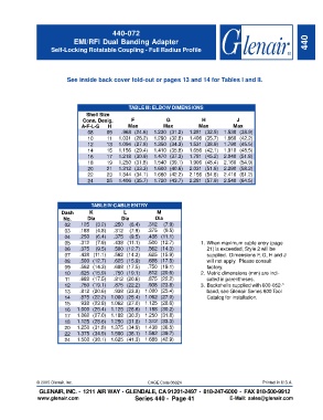
440-072
                             EMI/RFI Dual Banding Adapter                                                             440
                    Self-Locking Rotatable Coupling - Full Radius Profile


                          See inside back cover fold-out or pages 13 and 14 for Tables I and II.


                                                  TABLE III: ELBOW DIMENSIONS
                                  Shell Size
                                Conn. Desig.       F            G             H            J
                                A-F-L-S   H       Max          Max          Max          Max
                                  08     09    .968 (24.6)  1.230 (31.2)  1.281 (32.5)  1.530 (38.9)
                                  10      11  1.031 (26.2)  1.290 (32.8)  1.406 (35.7)  1.660 (42.2)
                                  12     13   1.094 (27.8)  1.350 (34.3)  1.531 (38.9)  1.790 (45.5)
                                  14     15   1.156 (29.4)  1.410 (35.8)  1.656 (42.1)  1.910 (48.5)
                                  16     17   1.218 (30.9)  1.470 (37.3)  1.781 (45.2)  2.040 (51.8)
                                  18     19   1.250 (31.8)  1.540 (39.1)  1.906 (48.4)  2.160 (54.9)
                                  20     21   1.312 (33.3)  1.600 (40.6)  2.031 (51.6)  2.290 (58.2)
                                  22     23   1.344 (34.1)  1.660 (42.2)  2.156 (54.8)  2.410 (61.2)
                                  24     25   1.406 (35.7)  1.720 (43.7)  2.281 (57.9)  2.540 (64.5)


                                    TABLE IV:CABLE ENTRY
                        Dash       K            L            M
                         No.      Dia          Dia          Dia
                          02   .125  (3.2)  .250  (6.4)  .312  (7.9)
                          03   .188  (4.8)  .312  (7.9)  .375  (9.5)
                          04   .250  (6.4)  .375  (9.5)  .438 (11.1)
                          05   .312  (7.9)  .438 (11.1)  .500 (12.7)         1. When maximum cable entry (page
                          06   .375  (9.5)  .500 (12.7)  .562 (14.3)           21) is exceeded, Style 2 will be
                          07   .438 (11.1)  .562 (14.3)  .625 (15.9)           supplied.  Dimensions F, G, H and J
                          08   .500 (12.7)  .625 (15.9)  .688 (17.5)           will not apply.  Please consult
                          09   .562 (14.3)  .688 (17.5)  .750 (19.1)           factory.
                          10   .625 (15.9)  .750 (19.1)  .812 (20.6)         2. Metric dimensions (mm) are indi-
                          11   .688 (17.5)  .812 (20.6)  .875 (22.2)           cated in parentheses.
                          12   .750 (19.1)  .875 (22.2)  .938 (23.8)         3. Backshells supplied with 600-052-*
                          13   .812 (20.6)  .938 (23.8) 1.000 (25.4)           band, see Glenair Series 600 Tool
                          14   .875 (22.2)  1.000 (25.4) 1.062 (27.0)          Catalog for installation.
                          15   .938 (23.8)  1.062 (27.0) 1.125 (28.6)
                          16  1.000 (25.4)  1.125 (28.6) 1.188 (30.2)
                          17  1.062 (27.0)  1.188 (30.2) 1.250 (31.8)
                          18  1.125 (28.6)  1.250 (31.8) 1.312 (33.3)
                          20  1.250 (31.8)  1.375 (34.9) 1.438 (36.5)
                          22  1.375 (34.9)  1.500 (38.1) 1.562 (39.7)
                          24  1.500 (38.1)  1.625 (41.3) 1.688 (42.9)


               © 2005 Glenair, Inc.                      CAGE Code 06324                             Printed in U.S.A.
                GLENAIR, INC. • 1211 AIR WAY •   GLENDALE, CA 91201-2497 •    818-247-6000 •  FAX 818-500-9912
               www.glenair.com                      Series 440 -  Page 41               E-Mail: sales@glenair.com