
Page 317 - Circular Connector Backshells and Accessories
P. 317
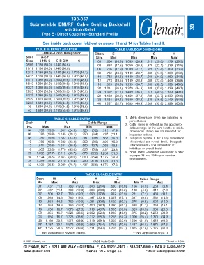
390-057
                   Submersible  EMI/RFI  Cable  Sealing  Backshell
                                        with Strain Relief                                                           39
                          Type E - Direct Coupling - Standard Profile

                           See inside back cover fold-out or pages 13 and 14 for Tables I and II.

                      TABLE III: FRONT ADAPTER                        TABLE IV: ELBOW DIMENSIONS
                           J Max - Conn. Designator       Elbow      E           F           G           H
                Shell     A-E-F                            Size    Max          Max         Max         Max
                 Size    J-H-L-S   D-B-G-K      C           03   .664 (16.9) 1.039 (26.4)  .810 (20.6) 1.179 (29.9)
                 08/09 1.180 (30.0) 1.440 (36.6)            04   .688 (17.5) 1.059 (26.9)  .870 (22.1) 1.239 (31.5)
                 10/11 1.180 (30.0) 1.440 (36.6)            06   .705 (17.9) 1.089 (27.7)  .920 (23.4) 1.309 (33.2)
                 12/13 1.180 (30.0) 1.440 (36.6) 1.735 (44.1)  08  .732 (18.6) 1.109 (28.7)  .980 (24.9) 1.369 (34.8)
                 14/15 1.180 (30.0) 1.440 (36.6) 1.915 (48.6)  10  .732 (18.6) 1.109 (28.7)  .980 (24.9) 1.369 (34.8)
                 16/17 1.380 (35.0) 1.560 (39.6) 1.915 (48.6)  12  .773 (19.6) 1.139 (28.9)  1.080 (27.4) 1.449 (36.8)
                 18/19 1.380 (35.0) 1.560 (39.6) 1.915 (48.6)  16  .823 (20.9) 1.209 (30.7)  1.200 (30.5) 1.599 (40.6)
                 20/21 1.380 (35.0) 1.560 (39.6) 1.915 (48.6)  20  1.041 (26.4) 1.379 (34.9)  1.480 (37.6) 1.839 (46.7)
                 22/23 1.380 (35.0) 1.560 (39.6) 1.915 (48.6)  24  1.092 (27.7) 1.419 (36.0)  1.610 (40.9) 1.929 (49.0)
                 24/25 1.380 (35.0) 1.560 (39.6) 1.915 (48.6)  28  1.138 (28.9) 1.469 (37.3)  1.720 (43.7) 2.039 (51.8)
                 28/29 1.610 (40.9) 1.560 (39.6) 1.915 (48.6)  32  1.184 (30.1) 1.509 (38.3)  1.830 (46.5) 2.149 (54.6)
                 32/33 1.610 (40.9) 1.750 (44.5) 1.915 (48.6)  40  1.287 (32.7) 1.609 (40.9)  2.080 (52.8) 2.399 (60.9)
                  36  1.610 (40.9) 1.750 (44.5) 1.915 (48.6)
                  40  1.610 (40.9) 2.190 (55.6) 1.915 (48.6)


                                  TABLE X: CABLE ENTRY                      1. Metric dimensions (mm) are indicated in
                                                                               parentheses.
                 Dash       T            V            Cable Range           2. Cable range is defined as the accommo-
                 No.      Max          Max           Min         Max           dations range for the wire bundle or cable.
                  04    .780 (19.8)  .957 (24.3)  .125  (3.2)  .312  (7.9)     Dimensions shown are not intended for
                  06    .780 (19.8)  1.145 (29.1)  .250  (6.4)  .437 (11.1)    inspection criteria.
                  08    .780 (19.8)  1.332 (33.8)  .387  (9.8)  .562 (14.3)  3. Designate Symbol T  for 3 ring termination
                  10    .780 (19.8)  1.332 (33.8)  .350  (8.9)  .625 (15.9)    of individual and overall braid.  Designate
                  12    .811 (20.6)  1.551 (39.4)  .500 (12.7)  .750 (19.1)    D for standard 2 ring termination of
                  16    .905 (23.0)  1.770 (45.0)  .625 (15.9)  .937 (23.8)    individual or overall braid.
                  20   1.092 (27.7)  2.113 (53.7)  .875 (22.2) 1.250 (31.8)  4. When using Connector Designator B refer
                                                                               to pages 18 and 19 for part number
                  24   1.124 (28.5)  2.363 (60.0)  1.000 (25.4) 1.375 (34.9)   development.
                  28   1.399 (35.5)  2.770 (70.4)  1.250 (31.8) 1.625 (41.3)
                  32   1.399 (35.5)  3.020 (76.7)  1.437 (36.5) 1.875 (47.6)

                                                    TABLE XI: CABLE ENTRY
                       Dash      W           X            Y            Z             Cable Range
                        No.     Max         Max          Max          Max        Min **        Max
                        03*  .437 (11.1)  .760 (19.3)  .843 (21.4)  .630 (16.0)  .156  (4.0)  .250  (6.4)
                        04*  .437 (11.1)  .760 (19.3)  .906 (23.0)  .755 (19.2)  .188  (4.8)  .312  (7.9)
                        06*  .500 (12.7)  .760 (19.3) 1.093 (27.8)  .942 (23.9)  .281  (7.1)  .438 (11.1)
                        08   .563 (14.3)  .760 (19.3) 1.187 (30.1)  1.067 (27.1)  .387  (9.8)  .562 (14.3)
                        10   .563 (14.3)  .760 (19.3) 1.281 (32.5)  1.192 (30.3)  .375  (9.5)  .625 (15.9)
                        12   .563 (14.3)  .760 (19.3) 1.500 (38.1)  1.380 (35.1)  .438 (11.1)  .750 (19.1)
                        16   .656 (16.7)  1.073 (27.3) 1.719 (43.7)  1.535 (39.0)  .625 (15.9)  .938 (23.8)
                        20   .656 (16.7)  1.323 (33.6) 2.062 (52.4)  1.848 (46.9)  .875 (22.2)  1.250 (31.8)
                        24   .656 (16.7)  1.323 (33.6) 2.312 (58.7)  2.255 (57.3) 1.000 (25.4)  1.375 (34.9)
                        28  1.188 (30.2)  1.572 (39.9) 2.719 (69.1)  2.505 (63.6) 1.250 (31.8)  1.625 (41.3)
                        32* 1.187 (30.1)  1.572 (39.9) 2.969 (75.4)  2.755 (70.0) 1.437 (36.5)  1.875 (47.6)
                        40* 1.125 (28.6)  1.572 (39.9) 3.531 (89.7)  3.255 (82.7) 1.875 (47.6)  2.375 (60.3)
                         *  Not available in Style M clamp.                                                    ** Not Applicable Style D


               © 2005 Glenair, Inc.                      CAGE Code 06324                             Printed in U.S.A.
               GLENAIR, INC. • 1211 AIR WAY • GLENDALE, CA 91201-2497 • 818-247-6000 • FAX 818-500-9912
               www.glenair.com                       Series 39 -  Page 55               E-Mail: sales@glenair.com